Bearing lock and locking and unlocking method

A locking and unlocking technology, applied in the field of unmanned aerial vehicle systems, can solve the problems of complex structure, difficult automation and heavy weight of the door switch drive mechanism, and achieve the effect of light weight, ensuring connection strength and rigidity, and strong bearing capacity.

Pending Publication Date: 2017-11-17
丰翼科技(深圳)有限公司
View PDF14 Cites 5 Cited by
  • Summary
  • Abstract
  • Description
  • Claims
  • Application Information

AI Technical Summary

Problems solved by technology

[0004] For the one-piece structure, the structure of the door switch drive mechanism is c

Method used


Image

  • Bearing lock and locking and unlocking method
  • Bearing lock and locking and unlocking method
  • Bearing lock and locking and unlocking method

Examples


Embodiment 1

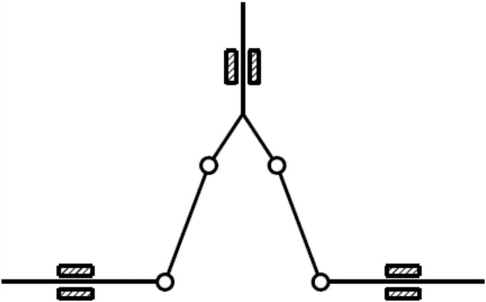
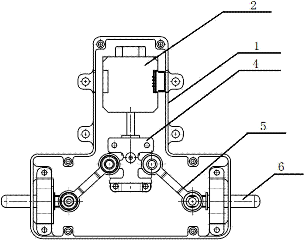
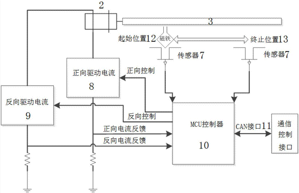
[0042] Such as Figure 1-4 As shown, the description method of this embodiment is described by taking the direction shown in the drawings as an example. This embodiment provides a load lock, which includes a convex housing 1, a geared motor 2 is arranged in the housing 1, the output shaft of the geared motor 2 is connected with a lead screw 3, and the lead screw 3 is threaded with a nut seat 4, When the leading screw 3 rotates, the nut seat 4 moves between the initial position 12 and the end position 13 along the leading screw 3, and the two sides of the nut seat 4 are respectively connected with the rocking arm 5 through the rotating shaft through the rotating shaft, and the nut seat 4 and the rocking arm 5. The bearing at the rotating joint is a ball bearing. The rocking arm 5 is respectively connected to a lock pin 6 through a rotating shaft. The bearing at the rotating joint between the rocking arm 5 and the locking pin 6 is a linear motion bearing. The end of the locking ...

Embodiment 2

[0059] The features of this embodiment that are the same as those of Embodiment 1 will not be described in detail. The features of this embodiment that are different from Embodiment 1 are:

[0060] The carrying lock of the present embodiment comprises a convex housing 1, a geared motor 2 is arranged in the housing 1, the output shaft of the geared motor 2 is connected with a lead screw 3, the lead screw 3 is threaded with a nut seat 4, and the lead screw 3 When rotating, the nut seat 4 moves between the initial position 12 and the end position 13 along the lead screw 3, the two sides of the nut seat 4 are respectively connected with the rocker arm 5 by the rotating shaft through the rotating shaft, and the nut seat 4 is rotationally connected with the rocker arm 5 The bearing at the position is a ball bearing, and the rocker arm 5 is connected with a lock pin 6 through a rotating shaft, and the bearing at the rotation joint between the rocker arm 5 and the lock pin 6 is a linea...

Embodiment 3

[0069] The features of this embodiment that are the same as those of Embodiment 1 will not be described in detail. The features of this embodiment that are different from Embodiment 1 are:

[0070] In the carrying lock of this embodiment, the power mechanism is sufficient to reciprocate along the starting position and the end position in the linear direction. The power mechanism in this implementation is a cylinder and a fixed seat. The piston rod of the cylinder is connected to the fixed seat. The two sides are connected in rotation with the rocker arm through the rotating shaft respectively, and the bearings at the rotation connection of the fixed seat and the rocker arm are ball bearings.

[0071] The controller controls the start position and end position of the reciprocating motion of the power mechanism through the sensor.

[0072] A method for locking and unlocking a bearing lock is provided, comprising the following steps:

[0073] The piston rod of the air cylinder r...


PUM


Abstract

The invention relates to a bearing lock and a locking and unlocking method. According to the bearing lock, a shell is internally provided with a power mechanism which does straight reciprocating motion, the two sides of the power mechanism are each rotationally connected with a rocker arm, the rocker arms are each rotationally connected with a lockpin, the end portions of the lockpins penetrate out of the shell, and locking and unlocking actions of the bearing lock are achieved. The structure is simple, and the weight is low. The force which is applied by the power mechanism acts on the lockpins through the rocker arms, and the stress directions of the lockpins are perpendicular to the force application direction of the power mechanism. By means of the extending and retracting, relative to the shell, of the lockpins, the power mechanism and the two lockpins form a triangle all the time no matter how the power mechanism moves in the liner direction, the triangle is simple in structure and mostly is high in stability, and then the bearing capacity of the bearing lock is high. While it is guaranteed that the bearing lock can be connected with a warehouse and an unmanned aerial vehicle, the bearing lock can bear the weight of express items in the warehouse and overload, it is further guaranteed that the warehouse cannot move, and the connection strength and rigidity are guaranteed.

Description

technical field [0001] The invention relates to an unmanned aerial vehicle system, in particular to a bearing lock and a locking and unlocking method. Background technique [0002] In the logistics industry, the UAV system is used to store the transported logistics express by connecting with the warehouse. In order to improve the operational efficiency of UAVs, one UAV can correspond to multiple general-purpose warehouses, and the warehouses and UAVs can be separated or integrated. [0003] During the transportation of the express, it is necessary to place the express in the warehouse, and then close the cargo door to protect the express. [0004] For the one-piece structure, the structure of the door switch drive mechanism is complex and heavy, and it is difficult to automate the entry and exit of express shipments into and out of the warehouse. [0005] Therefore, the separate structure of the warehouse and the UAV is generally selected. For the detached warehouse and th...

Claims


Application Information

Patent Timeline
IPC IPC(8): F16B1/00F16B1/02F16B1/04
CPCF16B1/02F16B1/04F16B2200/91F16B2200/89
Inventor 彭兴林张浩周韦博
Owner 丰翼科技(深圳)有限公司
Why Eureka
Try Eureka