Ultrasonic nondestructive testing method based on travel time tomography and reverse time migration imaging

A technology of reverse time migration imaging and travel time tomography, applied in the analysis of solids using sonic/ultrasonic/infrasonic waves, material analysis using sonic/ultrasonic/infrasonic waves, measurement devices, etc. There are few problems involved, achieving the effect of broad application prospects, strong practicability and high accuracy

Active Publication Date: 2017-11-17
XIAMEN UNIV
View PDF4 Cites 9 Cited by
  • Summary
  • Abstract
  • Description
  • Claims
  • Application Information

AI Technical Summary

Benefits of technology

This new technique uses two different techniques - one works well with conventional means like X ray radar (XR) or magnetic particle inspection (MPI), while another work better at detecting small flaws called cracks that may be hidden within materials during manufacturing processes. By combining these technologies together, this process allows us to accurately determine if there are any flaw(es).

Problems solved by technology

This patented technical problem addressed in this patents relates to improving the efficiency and precision of inspecting material properties during non destructively tested inspections like sonar techniques. Traditional approaches have limitations with regard to both speed and depth penetrating capabilities but they provide more precise results than existing methods at least partly because these methods require higher levels of expertise and skill compared to newer advanced methods.

Method used


Image

  • Ultrasonic nondestructive testing method based on travel time tomography and reverse time migration imaging
  • Ultrasonic nondestructive testing method based on travel time tomography and reverse time migration imaging
  • Ultrasonic nondestructive testing method based on travel time tomography and reverse time migration imaging

Examples


Embodiment Construction

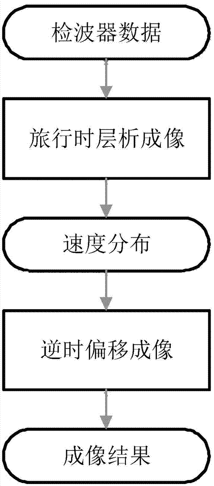
[0045] Such as figure 1 As shown, the present invention is based on the ultrasonic nondestructive testing method of travel time tomography and reverse time migration imaging, which specifically includes the following steps:

[0046] Step 1. Set multiple sets of ultrasonic excitation sources and detectors around the structure to be tested, and excite ultrasonic signals at the location of the excitation source, and collect ultrasonic transmission signals at the location of the detector;

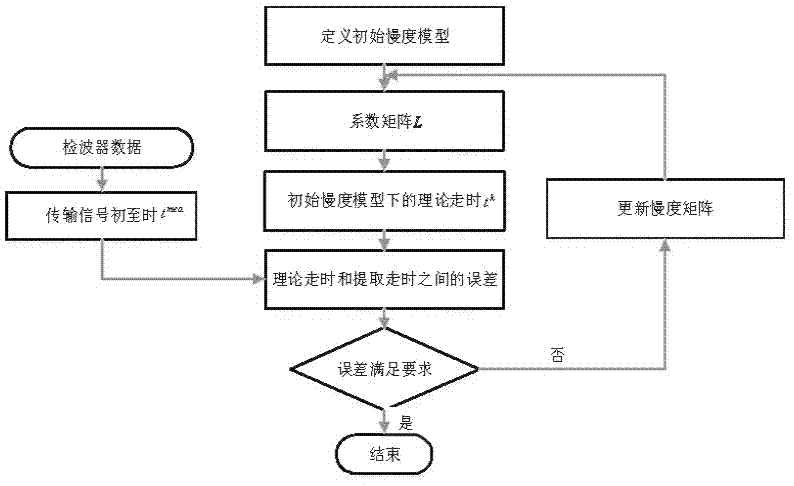
[0047] Step 2. Extract the arrival time t of the first wave of each ultrasonic transmission signal mea ;

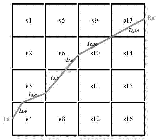
[0048] Step 3, if figure 2 As shown in , the cross-sectional area of ​​the structure is divided into discrete grids, numbered in a certain order, and the initial supersonic velocity in each grid is set to obtain an initial slowness model s 0 , using the relationship between travel time and slowness, the location of the detector and excitation source, and the first arrival travel time t...


PUM


Abstract

The invention relates to an ultrasonic nondestructive testing method based on travel time tomography and reverse time migration imaging. The method includes: acquiring ultrasonic velocity distribution within a to-be-tested structure section by travel time tomography technique, taking the ultrasonic velocity distribution as an initial velocity model of reverse time migration imaging, and then employing reverse time migration imaging technique for imaging the internal defect of the to-be-tested structure. The method provided by the invention can achieve high resolution imaging of concrete internal voids, concrete-filled steel tube stripping and other defects so as to acquire the position, size, shape and other information of the defects, and has broad practical application prospects.

Description


Claims


Application Information

Patent Timeline
Owner XIAMEN UNIV
Why Eureka
Try Eureka