

Dual-power automatic change-over switch
An automatic transfer switch and dual power supply technology, which is applied to electric switches, power devices inside switches, circuits, etc., can solve problems such as poor power supply stability and high-voltage safety hazards, and achieve low voltage usage, low equipment cost, and long service life. Effect
- Summary
- Abstract
- Description
- Claims
- Application Information
AI Technical Summary
Problems solved by technology
Method used
Image

Examples
Embodiment 1
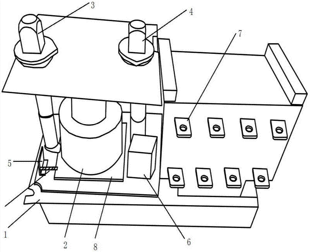
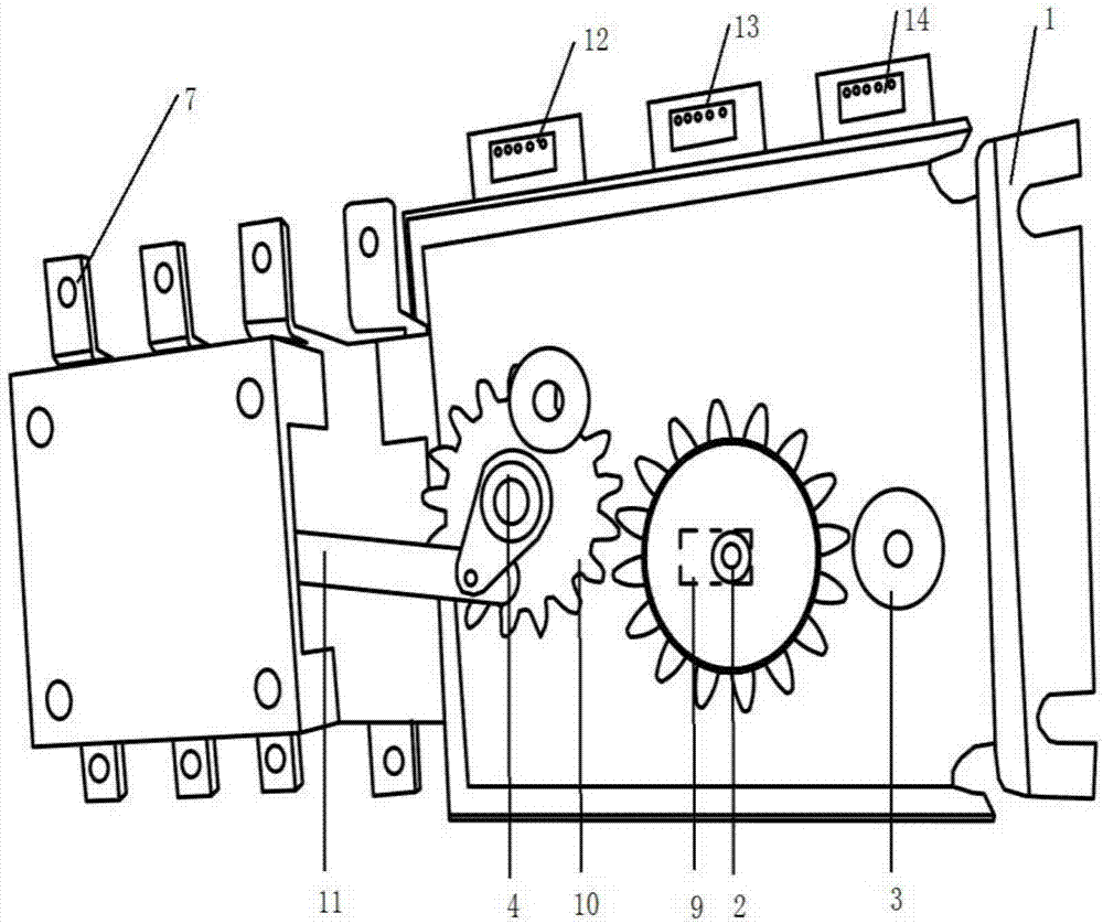
[0019] Example 1, such as figure 1 , figure 2 As shown, the dual power automatic transfer switch includes a housing 1, a geared motor 2, a relay 6, a dual power converter 7, a gear set 10 and a control link 11; the geared motor 2 is fixed on the housing 1, specifically through the geared motor 2 ends of the gear to clamp the shell 1 between the geared motor 2 and the gear, and then complete the fixing of the geared motor 2; the gear set 10 is connected to the control link 11; the control link 11 is connected to the dual power converter 7; The power automatic transfer switch also includes an adjustment rotating shaft 3 and a manual rotating shaft 4 . In the manual state, turn the manual shaft 4, the gear set 10 connected to the lower part of the manual shaft 4 will drive the control connecting rod 11 to move, further control the connecting rod 11 and then control the adjustment mechanism inside the dual power converter 7 to realize the conversion of up and down isolation reg...
Embodiment 2
[0020] Example 2 as figure 1 , figure 2 Said, further on the basis of the above technical solution, the geared motor 2 is fixed on the shell 1 through gears, and a slide rail 9 is arranged on the shell 1 at the connection between the geared motor 2 and the shell 1, so that the geared motor 2. It can move left and right along the slide rail 9 under the action of external force, so as to realize the engagement and separation of the gear at the lower part of the geared motor 2 and the gear set 10. When the geared motor 2 and the gear set 10 are in a separated state, the alignment of the gear set cannot be completed The control of 10, thereby needs to adjust manual rotating shaft 4 to finish, regulates control. When the gear at the lower end of the geared motor 2 is in a combined state with the gear set 10, the automatic control of the geared motor 2 to the dual power converter 7 can be realized. The lower end of the adjusting shaft is provided with a regulating piece 16, and t...
Embodiment 3
[0021]Embodiment 3 Further on the basis of the technical solution of Embodiment 2, a fixed base plate 8 is also provided between the lower end of the geared motor 2 and the lower gear of the geared motor 2, and the fixed base plate 8 is fixedly connected to the bottom end of the geared motor 2, One end of the adjustment spring 15 is fixed on the fixed piece 5, and the other end is fixed on the fixed bottom plate 8. The fixed floor 8 can slide relative to the housing 1 along the slide rail, thereby driving the reduction motor 2 to slide, thereby realizing the connection between the reduction motor 2 and the gear set 10. union and separation. A fixed base is set between the lower part of the geared motor and the shell, so that the spring can be directly fixed on the fixed base, so that there is no need to worry about the work of the motor being affected by fixing the spring on the geared motor. In addition, the design of the fixed base also makes the geared motor slide along the ...
PUM
 Abstract
Description
Claims
Application Information