Assembly and disassembly device of high-pressure joint rotor of aero-engine

An aero-engine and engine casing technology is applied in the field of disassembly and assembly devices of aero-engine high-pressure combined rotors, and can solve the problems of easily damaged peripheral parts, easily damaged centrifugal impeller and high-pressure shaft assembly state, etc.

Active Publication Date: 2019-08-13
CHINA HANGFA SOUTH IND CO LTD
View PDF6 Cites 0 Cited by
  • Summary
  • Abstract
  • Description
  • Claims
  • Application Information

AI Technical Summary

Problems solved by technology

[0004] The invention provides a disassembly and assembly device for the high-pressure combined rotor of an aero-engine to solve the technical problems that the existing high-pressure combined rotor disassembly and assembly method easily destroys the assembly state of the centrifugal impeller and the high-pressure shaft; and easily damages peripheral parts

Method used


Image

  • Assembly and disassembly device of high-pressure joint rotor of aero-engine
  • Assembly and disassembly device of high-pressure joint rotor of aero-engine

Examples


Embodiment Construction

[0023] The embodiments of the present invention will be described in detail below with reference to the accompanying drawings, but the present invention can be implemented in various ways defined and covered below.

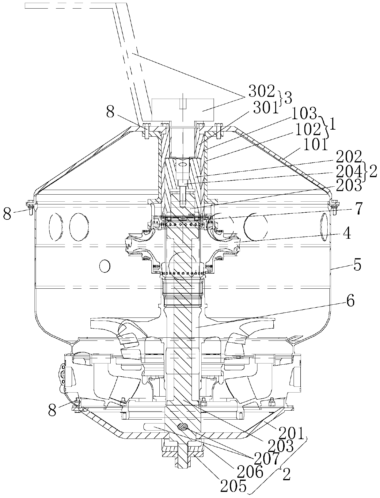
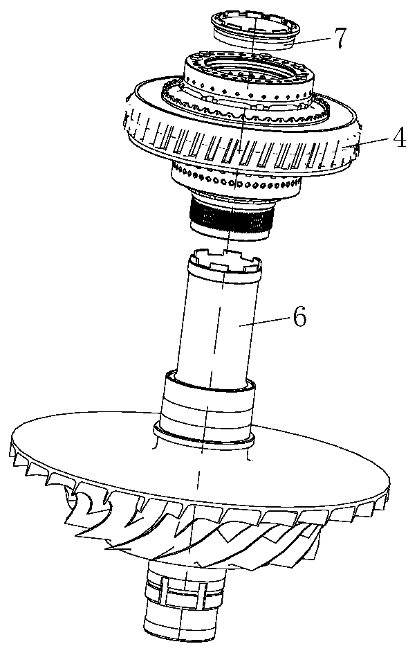
[0024] figure 1 It is a structural schematic diagram of the assembly and disassembly device of the high-pressure combined rotor of the aero-engine in the preferred embodiment of the present invention; figure 2 It is a structural schematic diagram of the high-pressure combined rotor of an aero-engine in a preferred embodiment of the present invention.

[0025] Such as figure 1 and figure 2 As shown, the assembly and disassembly device of the high-pressure combined rotor of the aero-engine in this embodiment includes a first fixing mechanism 1 for fixing the high-pressure turbine rotor assembly 4 of the high-pressure combined rotor on the first end surface of the engine case 5, and a first fixing mechanism 1 for fixing The high-pressure shaft 6 of the high-pres...


PUM


Abstract

The invention discloses a dismounting device for an aero-engine high-pressure combined rotor. The dismounting device comprises a first fixing mechanism, a second fixing mechanism and a force applying mechanism, wherein the first fixing mechanism is used for fixing a high-pressure turbine rotor component of a high-pressure combined rotor on a first end face of an engine cast; the second fixing mechanism is used for fixing a high-pressure shaft of the high-pressure combined rotor on a second end face of the engine cast; the force applying mechanism is used for penetrating through the first fixing mechanism along an axial direction of the high-pressure combined rotor and is connected with a gland nut of the high-pressure combined rotor so as to dismount the gland nut in the manner of twisting; the first fixing mechanism is used for fixing the structure of the high-pressure turbine rotor component, so as to prevent the high-pressure turbine rotor component from being influenced by the dismounting of the gland nut and rotating along circumferential direction; the second fixing mechanism is used for fixing the structure of a high-pressure shaft, so as to prevent the high-pressure shaft from being influenced by the dismounting of the gland nut and rotating along circumferential direction; the condition that the aero-engine high-pressure combined rotor meets the assembling technical requirement without influence on the surrounding part structures can be guaranteed.

Description

technical field [0001] The invention relates to the technical field of aero-engine structural assembly, in particular to a disassembly and assembly device for an aero-engine high-pressure combined rotor. Background technique [0002] When assembling the core machine of a certain type of aero-engine, the centrifugal impeller assembly, the high-pressure shaft (threaded at both ends, respectively connected to the centrifugal impeller and the compression nut), and the high-pressure turbine rotor assembly need to be assembled into the assembled casing in sequence. Specific assembly steps: 1. Install the centrifugal impeller into the casing; 2. Screw the high-pressure shaft into the centrifugal impeller with a tightening torque of 73-74N m; 3. Install the high-pressure turbine rotor assembly on the inner journal of the centrifugal impeller, and use The compression nut is compressed, and the tightening torque is 1300N·m. [0003] When assembling the compression nut, due to the exc...

Claims


Application Information

Patent Timeline
Patent Type & Authority Patents(China)
IPC IPC(8): B25B27/00
CPCB25B27/00
Inventor 庞文婷周斌罗坚程碧玉陈鹰
Owner CHINA HANGFA SOUTH IND CO LTD
Why Eureka
Try Eureka