Aero-engine low-pressure turbine rotor hoisting device and method

A technology for aero-engines and low-pressure turbines, applied in the field of aero-engines, can solve the problems of complex hoisting devices, low efficiency, and inability to meet the hoisting requirements of different levels of rotors, and achieve safety and stability, good safety, and versatility strong effect

Inactive Publication Date: 2020-01-07
AECC COMML AIRCRAFT ENGINE CO LTD
View PDF5 Cites 0 Cited by
  • Summary
  • Abstract
  • Description
  • Claims
  • Application Information

AI Technical Summary

Problems solved by technology

[0011] The technical problem to be solved by the present invention is to provide an aero-engine low-pressure turbine rotor hoisting device and its method in order to overcome the defects of the hoisting device in the prior art, such as complex structure, low efficiency, and inability to meet the hoisting requirements of rotors of different stages.

Method used


Image

  • Aero-engine low-pressure turbine rotor hoisting device and method
  • Aero-engine low-pressure turbine rotor hoisting device and method
  • Aero-engine low-pressure turbine rotor hoisting device and method

Examples


Embodiment Construction

[0066] In order to make the above objects, features and advantages of the present invention more comprehensible, specific implementations of the present invention will be described in detail below in conjunction with the accompanying drawings.

[0067] Embodiments of the present invention will now be described in detail with reference to the accompanying drawings. Reference will now be made in detail to the preferred embodiments of the invention, examples of which are illustrated in the accompanying drawings. Wherever possible, the same numbers will be used throughout the drawings to refer to the same or like parts.

[0068] In addition, although the terms used in the present invention are selected from well-known and commonly used terms, some terms mentioned in the description of the present invention may be selected by the applicant according to his or her judgment, and the detailed meanings thereof are set forth herein described in the relevant section of the description. ...


PUM


Abstract

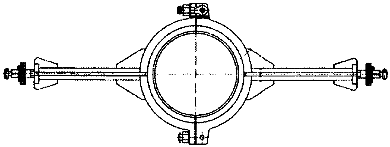
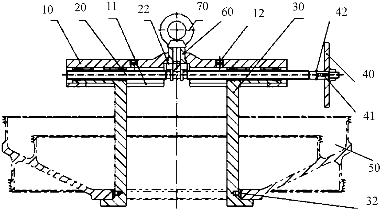
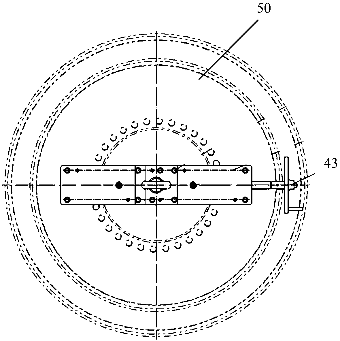
The invention provides an aero-engine low-pressure turbine rotor hoisting device and method. The aero-engine low-pressure turbine rotor hoisting device comprises an installation body, a rotating shaftinserted into the installation body, two hoisting rods and a hand wheel, wherein one end of each hoisting rod is installed in the installation body, the two hoisting rods are connected with the rotating shaft through at least two sections of symmetrical transmission thread pairs opposite in screwing direction, the radial distance between the two hoisting rods is adjusted, the other ends of the hoisting rods are located below the installation body and connected with a turbine rotor, the handle wheel is installed at the outer end of the rotating shaft and used for driving the rotating shaft torotate, rotation of the rotating shaft is converted into linear movement of the hoisting rods through the hand wheel, and then hoisting of the turbine rotor is achieved. The aero-engine low-pressure turbine rotor hoisting device and method achieve that stable hoisting of a rotor disk only utilizes an inner hole and an end face, so that a labyrinth seal and a threaded structure of the body piece are protected to the greatest extent, and assembling technology requirements of low-pressure turbine rotor and stator assembly are met.

Description

technical field [0001] The invention relates to the field of aero-engines, in particular to an aero-engine low-pressure turbine rotor hoisting device and method thereof. Background technique [0002] In the field of aero-engines, low-vortex stator assembly is an important part of aero-engine assembly, and there are many honeycomb and grate tooth structures in the unit body. At the same time, low-pressure turbines generally have many different size series, so it is necessary to design an adjustable, universal and reliable spreader. [0003] In addition, according to the assembly process, in order to protect the rotor grate and thread structure at all levels, the following two requirements must be met during the hoisting process: [0004] 1. The spreader is fixed at the center of the low-pressure turbine disk, so as to prevent the grate teeth and thread structures of the rotors at all levels from being damaged during the lifting process, and at the same time ensure the stabil...

Claims


Application Information

Patent Timeline
Patent Type & Authority Applications(China)
IPC IPC(8): B66C1/10
CPCB66C1/107
Inventor 张延陈栋权刘政良
Owner AECC COMML AIRCRAFT ENGINE CO LTD
Why Eureka
Try Eureka