

Symmetrical-gripping-jaw fixture capable of rotating 180 degrees
A clamping jaw and fixture technology, which is applied in the field of fixtures, can solve the problems of inability to install fixtures, small application scope, and low firmness of workpieces, and achieves the effect of reducing labor intensity and improving clamping.
- Summary
- Abstract
- Description
- Claims
- Application Information
AI Technical Summary
Problems solved by technology
Method used
Image

Examples
Embodiment 1
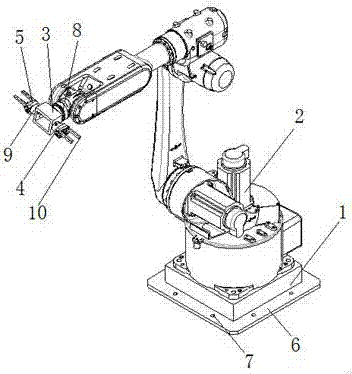
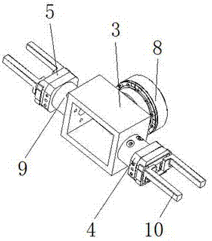
[0018] as attached figure 1 and 2 As shown, a symmetrical jaw fixture that can rotate by 180° includes a robot base 1, a robot 2, a flange mounting seat 3, a mounting plate 4 and a jaw 5, and is characterized in that: the robot 2 is set on the robot base 1, the flange mounting seat 3 is set on the robot 2 through the connecting shaft 8, and fixed blocks 9 are arranged on opposite sides of the flange mounting seat 3, and the mounting plate 4 is set on the fixed block 9 , the clamping jaw 5 is arranged on the mounting plate 4 , and a clamping rod 10 is arranged on the clamping jaw 5 .
[0019] Preferably, the robot base 1 is provided with a connection plate 6, and a connection hole 7 is provided on the connection plate 6, through the connection plate 6 and the connection hole 7, the stability of the robot 2 in the workpiece clamping and installation process can be improved performance, thereby improving the stability of workpiece clamping and installation.
[0020] Preferably...
Embodiment 2
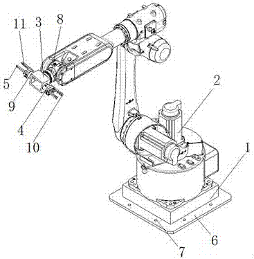
[0024] as attached image 3 and 4 As shown, a symmetrical jaw fixture that can rotate by 180° includes a robot base 1, a robot 2, a flange mounting seat 3, a mounting plate 4 and a jaw 5, and is characterized in that: the robot 2 is set on the robot base 1, the flange mounting seat 3 is set on the robot 2 through the connecting shaft 8, and fixed blocks 9 are arranged on opposite sides of the flange mounting seat 3, and the mounting plate 4 is set on the fixed block 9 , the clamping jaw 5 is arranged on the mounting plate 4 , and a clamping rod 10 is arranged on the clamping jaw 5 .
[0025] Preferably, the robot base 1 is provided with a connection plate 6, and a connection hole 7 is provided on the connection plate 6, through the connection plate 6 and the connection hole 7, the stability of the robot 2 in the workpiece clamping and installation process can be improved performance, thereby improving the stability of workpiece clamping and installation.
[0026] Preferably...
PUM
 Abstract
Description
Claims
Application Information