Forming mold for auxiliary instrument middle mounting support

A technology for mounting brackets and forming molds, which is applied to household appliances, other household appliances, household components, etc., can solve the problems affecting the molding quality of the auxiliary instrument mounting brackets and the low flatness of the workpiece surface, so as to improve the demolding quality and improve the injection molding. quality, the effect of improving the flatness

Inactive Publication Date: 2017-11-21
宁波斯穆汽车模具有限公司
View PDF4 Cites 4 Cited by
  • Summary
  • Abstract
  • Description
  • Claims
  • Application Information

AI Technical Summary

Problems solved by technology

[0003] The mounting bracket in the middle of the sub-instrument is a plastic part, and the whole structure is hard plastic injection molding. At present, the processing of the mounting bracket in the middle of the sub-instrument is processed by injection mold; hole, resulting in low surface flatness of the workpiece, which affects the molding quality of the mounting bracket in the middle of the sub-instrument

Method used


Image

  • Forming mold for auxiliary instrument middle mounting support
  • Forming mold for auxiliary instrument middle mounting support
  • Forming mold for auxiliary instrument middle mounting support

Examples


Embodiment Construction

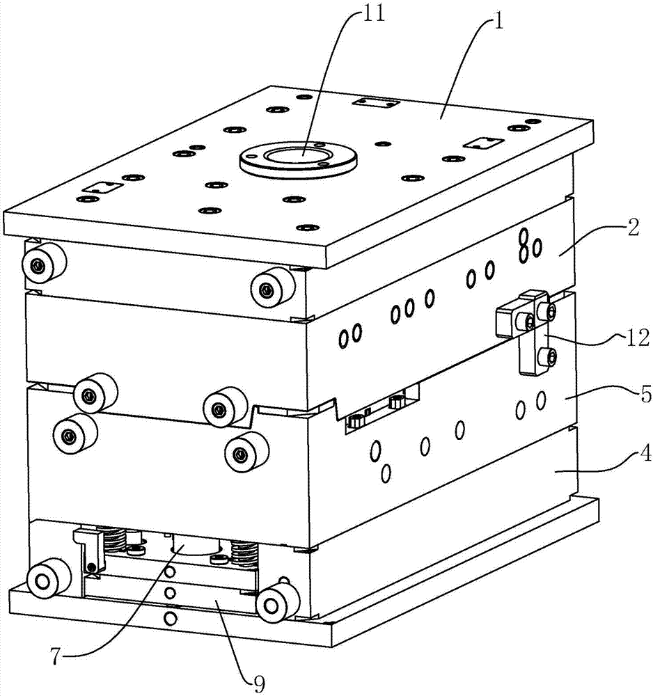
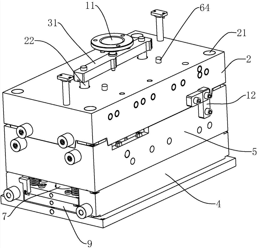
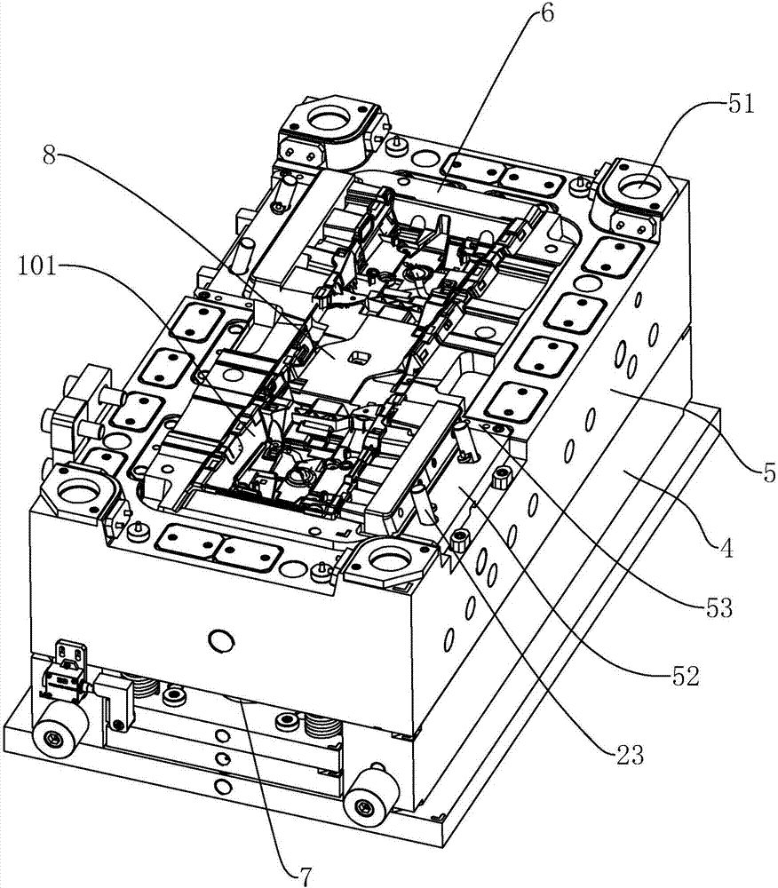
[0037] refer to Figure 1 to Figure 9 Further explain the forming mold of the mounting bracket in the middle of the auxiliary instrument.

[0038] A mold for forming a mounting bracket in the middle of an auxiliary instrument, such as figure 1 As shown, it includes fixed mold base plate 1, fixed mold plate 2 connected with fixed mold base plate 1, combined Figure 4 As shown, the upper mold core 3 connected to the fixed template 2, the movable mold seat plate 4, the movable template 5, and the combined image 3 As shown, the lower mold core 6 connected to the movable template 5 and the drive device 7 for driving the movable template 5 to reciprocate in the direction of the fixed template 2, and the upper mold core 3 and the lower mold core 6 cooperate to form a mold cavity 8; The driving device 7 can be a drive cylinder 10; a drive plate 9 is arranged between the movable template 5 and the movable mold base plate 4, and a drive plate 9 is provided between the movable mold ba...


PUM


Abstract

The invention discloses a forming mold for an auxiliary instrument middle mounting support. The forming mold comprises a fixed mold seat plate, a fixed mold plate, an upper mold core, a movable mold seat plate, a movable mold plate, a lower mold core, a driving device, a forming column, a vertical male mold insert, a hook face male mold insert, a side wall male mold insert, a forming male mold insert and a forming female mold insert. The fixed mold plate is provided with a guiding column, and the movable mold plate is slidably provided with a sliding block. The guiding column is arranged in the sliding block in a penetrating mode, the tail end of the guiding column is inserted in the movable mold plate and slidably connected with the movable mold plate, and an orientation assembly is arranged between the sliding block and the movable mold plate. A first punching male mold, a second punching male mold, a third punching male mold and a fourth punching male mold are connected to the sliding block. The forming column, the vertical male mold insert, the hook face male mold insert, the side wall male mold insert, the forming male mold insert, the forming female mold insert, the upper mold core and the lower mold core form the cavity wall of a model cavity. The auxiliary instrument middle mounting support is formed through integrated injection molding, the workpiece surface evenness of the auxiliary instrument middle mounting support is improved, and thus the forming quality of the auxiliary instrument middle mounting support of the middle of an auxiliary instrument is improved.

Description

technical field [0001] The invention relates to the technical field of injection molds for auto parts, more specifically, it relates to a molding mold for mounting brackets in the middle of an auxiliary instrument. Background technique [0002] With the rapid development of the car industry, especially the urgent need for the expansion of the domestic small car market, major OEMs require to improve the production efficiency of products; The assembly is like a window, which reflects the running status of the machine inside the car at any time; at the same time, the auxiliary instrument is the control center and supported object of some equipment, and is the most eye-catching part in the cab. It has both technical functions and artistic features. Function is one of the representatives of vehicle style. [0003] The mounting bracket in the middle of the sub-instrument is a plastic part, and the whole structure is hard plastic injection molding. At present, the processing of th...

Claims


Application Information

Patent Timeline
Patent Type & Authority Applications(China)
IPC IPC(8): B29C45/26B29C45/40B29L31/30
CPCB29C45/2602B29C45/4005B29L2031/3008
Inventor 章武杰
Owner 宁波斯穆汽车模具有限公司
Why Eureka
Try Eureka