
Rainwater harvesting device for garden irrigation

A rainwater collection device and gardening technology, which is applied to drinking water devices, water supply devices, watering devices, etc., can solve the problems of control, inability to clean umbrella cloth, and inability to arrange trees, so as to reduce floor space, facilitate irrigation, and avoid The effect of waterlogging

Inactive Publication Date: 2019-05-10
SOUTHWEST FORESTRY UNIVERSITY
View PDF1 Cites 0 Cited by
  • Summary
  • Abstract
  • Description
  • Claims
  • Application Information

AI Technical Summary

Problems solved by technology

The invention can be unfolded or folded for rainwater collection or suspended use, but the device cannot clean the umbrella cloth, and cannot be arranged around trees, which is not conducive to controlling the amount of water for garden irrigation

Method used


Image

  • Rainwater harvesting device for garden irrigation
  • Rainwater harvesting device for garden irrigation
  • Rainwater harvesting device for garden irrigation

Examples


specific Embodiment approach 1

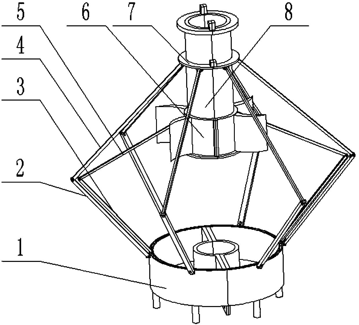
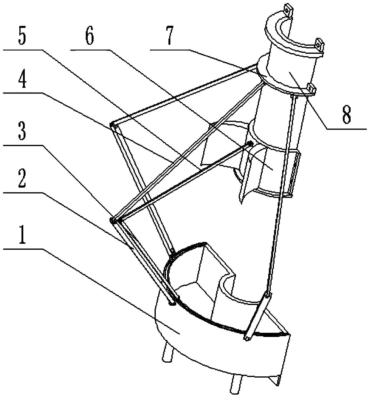
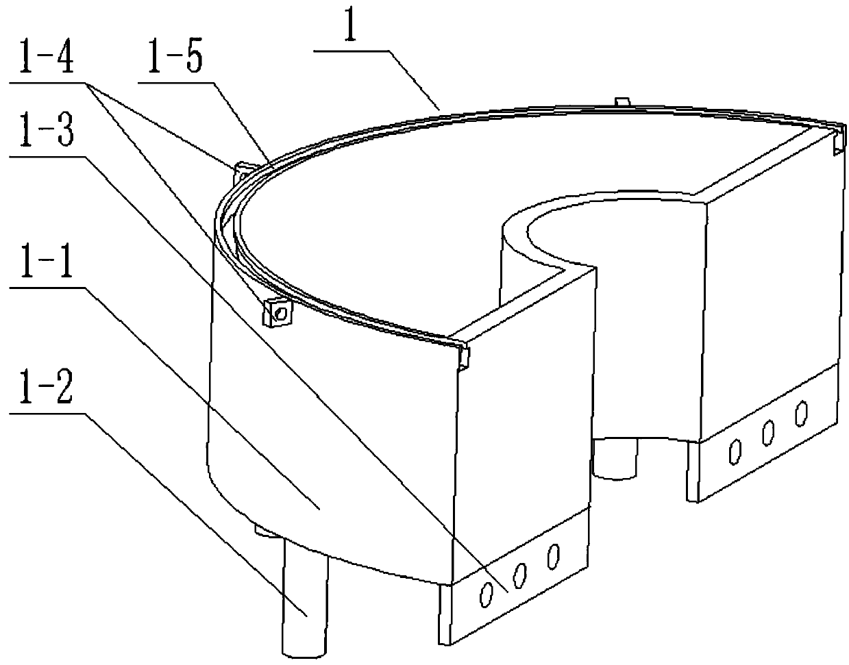
[0042] Combine below figure 1 , 2 , 3, 4, 5, 6, 7, and 8 illustrate this embodiment, a rainwater collection device for garden irrigation, including a water tank 1, a water collecting cloth support rod 2, a brush rod 3, a hinged connecting rod I4, and a hinged connecting rod II5 , impeller 6, connecting rod frame 7 and rotating shaft sleeve 8, described water tank 1 comprises annular water tank 1-1, water tank supporting leg 1-2, water tank connecting plate 1-3, water collecting cloth support bar seat 1-4 and T shaped groove 1-5, a plurality of water tank legs 1-2 are arranged at the lower end of the annular water tank 1-1, the inner side of the lower end surface of the annular water tank 1-1 is welded and connected to the water tank connecting plate 1-3, and the upper end of the outer wall of the annular water tank 1-1 is evenly arranged A plurality of water-collecting cloth support rod seats 1-4, and an inverted T-shaped groove 1-5 is arranged on the upper end of the outer w...

specific Embodiment approach 2

[0048] Combine below figure 1 , 2 , 3, 4, 5, 6, 7, and 8 illustrate this embodiment, and this embodiment will further describe Embodiment 1. A spring I is set between the link frame 7 and the upper baffle plate 8-3, and the spring I is in the pull In the extended state, when too much rainwater is collected on the upper end of the waterproof cloth, the supporting rod 2 of the water-collecting cloth passes through the hinged connecting rod I4 under the action of gravity, and pulls the connecting rod frame 7 to slide downward, further stretching the spring I; at the same time, the expanded area of ​​the waterproof cloth increases Larger, increasing the rainwater storage volume and collection area of ​​the device; moreover, the expansion of the tarpaulin can also prevent excessive rainwater from directly irrigating the roots of trees and causing waterlogging.

specific Embodiment approach 3

[0049] Combine below figure 1 , 2 , 3, 4, 5, 6, 7, and 8 describe this embodiment, and this embodiment will further explain Embodiment 1. A spring II9 is ​​arranged between the link frame 7 and the impeller 6, and the spring II9 is ​​always in a compressed state. II9 pushes the brush bar 3 through the hinged connecting rod II5, so that the combs of the brush bar 3 are in contact with the waterproof cloth, so as to ensure that the comb hairs can have a better brushing effect on the waterproof cloth.


PUM


Abstract

The invention relates to a rainwater collection device, in particular to a rainwater collection device for garden irrigation. The rainwater collection device comprises a water tank, water-collection-cloth supporting rods, brush rods, first hinging connecting rods, second hinging connecting rods, an impeller, a rod connecting frame and a rotating shaft sleeve. The water tank comprises annular water tank bodies, water-tank supporting legs, water-tank connecting plates, water-collection-cloth supporting rod bases and T-shaped grooves, wherein the multiple water-tank supporting legs are arranged at the lower ends of the annular water tank bodies, the inner sides of the lower end faces of the annular water tank bodies are connected with the water-tank connecting plates in a welded mode, the multiple water-collection-cloth supporting rod bases are evenly arranged at the upper ends of the outer side walls of the annular water tank bodies, and the inverted T-shaped grooves are formed in the upper ends of the outer tank walls of the annular water tank bodies. The rainwater collection device for garden irrigation can be arranged on the peripheries of trees in a surrounded mode, and the irrigation water volume of the trees is controlled; the developed area can also be increased, the rainwater collection capacity and area are enlarged, or the rainwater collection device is folded on a sunny day, the occupied area is reduced, and waterproof cloth cleaning can be carried out.

Description

technical field [0001] The invention relates to a rainwater collection device, more specifically a rainwater collection device for garden irrigation. Background technique [0002] In order to solve a series of problems such as water shortage, environment, and ecology, people pay attention to the collection and utilization of rainwater. Due to the limited cleanliness of rainwater itself, it is currently the direction of most rainwater collection to use it directly for agriculture or garden irrigation. Due to the shortage of water resources in the west of my country, rainwater harvesting devices have been developed for a long time in my country. [0003] For example, the patent application number is CN201410752112.2, a kind of rainwater collection device, the upper loop of the vertical rod has a sliding sleeve, a tension spring is arranged between the upper end surface of the sliding sleeve and the upper end of the vertical rod, and the lower part of the vertical rod is fixed...

Claims


Application Information

Patent Timeline
Patent Type & Authority Patents(China)
IPC IPC(8): E03B3/02B08B1/00A01G25/00
CPCY02A20/108
Inventor 延相东徐慧琳贾晓轩张洋王佳琪
Owner SOUTHWEST FORESTRY UNIVERSITY
Learn More