
Variable force application device

A force-applying device and variable technology, applied in the direction of measuring device, instrument, elasticity test, etc., can solve the problems of difficulty in replacement, difficulty in changing mass force, etc., and achieve the effect of easy adjustment

Pending Publication Date: 2017-11-21
BEIJING BRANCH JIKE DEV SCI & TECH
View PDF7 Cites 0 Cited by
  • Summary
  • Abstract
  • Description
  • Claims
  • Application Information

AI Technical Summary

Problems solved by technology

For the simulation of different working conditions, different mass forces need to be applied, but the masses are usually installed in the mechanism in a specific way, and it is difficult to replace them, that is, there is a problem that it is difficult to change the mass forces

Method used


Image

  • Variable force application device
  • Variable force application device
  • Variable force application device

Examples


no. 1 Embodiment approach

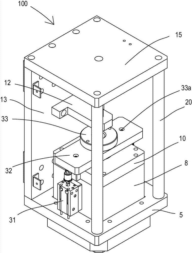
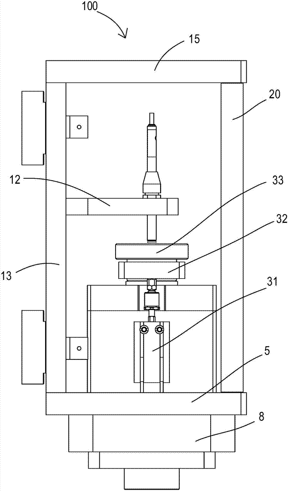
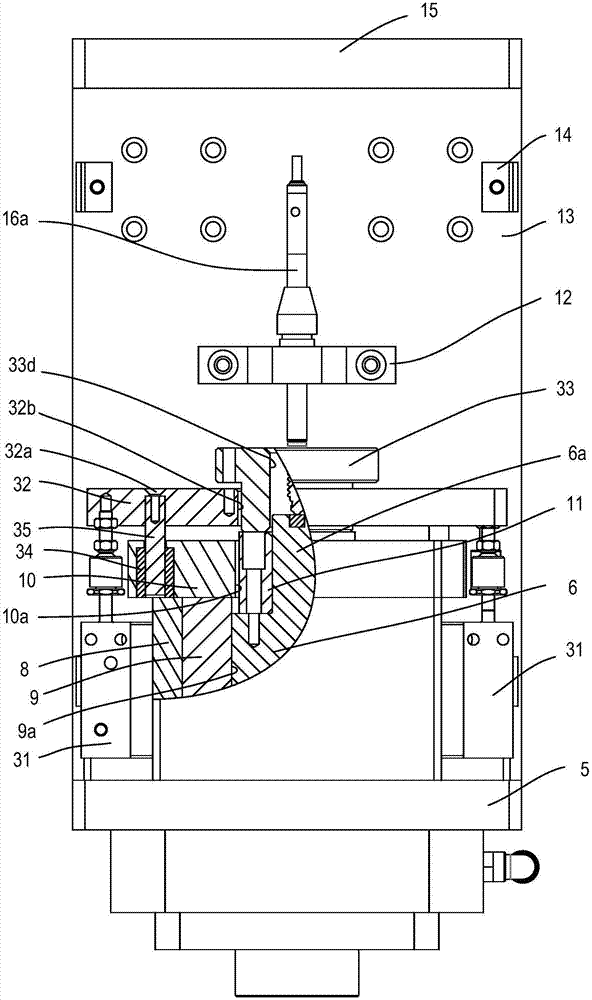
[0029] figure 1 It is a perspective view seen from the upper right of the urging force measurement mechanism 100 (an example of the variable urging device) according to the first embodiment. figure 2 It is a side view of the force measuring mechanism 100 . image 3 It is a cross-sectional view of the force measuring mechanism 100 viewed from the front. Figure 4 It is a partial cross-sectional view of the force measuring mechanism 100 viewed from the side.

[0030] Such as Figure 1~4 As shown, the variable force applying device 100 has an upper plate 15 and a lower plate 5 oppositely arranged, and a back plate 13 is connected between the rear of the upper plate 15 and the lower plate 5, and the upper plate 15 and the lower plate 5 A pair of left and right pillars 20 are arranged between the front part, and a pair of shield mounting blocks 14 are respectively arranged on the left and right sides of the back plate 13 along the up and down direction, and a shield (not shown)...

no. 2 Embodiment approach

[0052] Figure 5 It is a side view of the variable biasing device 200 in the second embodiment, Figure 6 Its oblique view.

[0053] The main difference between the second embodiment and the first embodiment is that in the first embodiment, there is one mass that can be lifted and lowered by the cylinder, while in the second embodiment there are two masses that can be driven by the cylinder. And lift up, put down the mass block.

[0054] Such as Figure 5 , 6 As shown, a pair of first air cylinders 231A and a pair of second air cylinders 231B are provided on the side wall of the mass block containing housing 208 inside, and the first air cylinders 231A and the second air cylinders 231B are alternately arranged in the circumferential direction. In other words, a pair of first air cylinders 231A are arranged oppositely, and a pair of second air cylinders 231B are arranged oppositely, and the pair of first air cylinders 231A drives the first lifting plate 232A to move up and ...


PUM


Abstract

The invention provides a variable force application device which can easily change applied mass force. The variable force application device is provided with a mass block (6) which applies mass force on a force-applied object, and a mass block holding housing holding the mass block. The mass block is configured with a weighting block (33). The mass block holding housing is provided with a weighting block driving mechanism. The weighting block driving mechanism drives the weighting block (33) to move between a first position and a second position. On the first position, the weighting block (33) is arranged on the mass block (6) and increases weight of the mass block (6). On the second position, the weighting block (33) leaves the mass block (6), and weight increment on the mass block (6) is relieved.

Description

technical field [0001] The present invention relates to a variable urging device that applies a predetermined mass force to an urging object such as a spring and can change the applied mass force. Background technique [0002] There is a force applying device. For example, in order to measure the workpiece, a mass block with a predicted quality is pressed on the workpiece (the object to be applied) to apply a certain mass force to the object to be measured, simulate the working conditions, and then measure its correlation. Size, so as to realize the measurement (detection) of the workpiece. For the simulation of different working conditions, different mass forces need to be applied. However, the mass block is usually installed in the mechanism in a specific way, and it is difficult to replace it, that is, there is a problem that it is difficult to change the mass force. Contents of the invention [0003] In view of this, an object of the present invention is to provide a ...

Claims


Application Information

Patent Timeline
Patent Type & Authority Applications(China)
IPC IPC(8): G01M13/00G01M5/00
CPCG01M5/005G01M13/00
Inventor 李芳程海洋雍占琦王伟丽
Owner BEIJING BRANCH JIKE DEV SCI & TECH
Learn More