Intelligent cabinet with kitchen waste treatment system
A treatment system and kitchen waste technology, applied in the field of cabinets, can solve the problems of increased organic matter content in sewers, difficult promotion and use, and easy garbage falling on the floor, etc., to achieve the effect of preventing clogging
- Summary
- Abstract
- Description
- Claims
- Application Information
AI Technical Summary
Problems solved by technology
Method used
Image
Examples
Embodiment 1
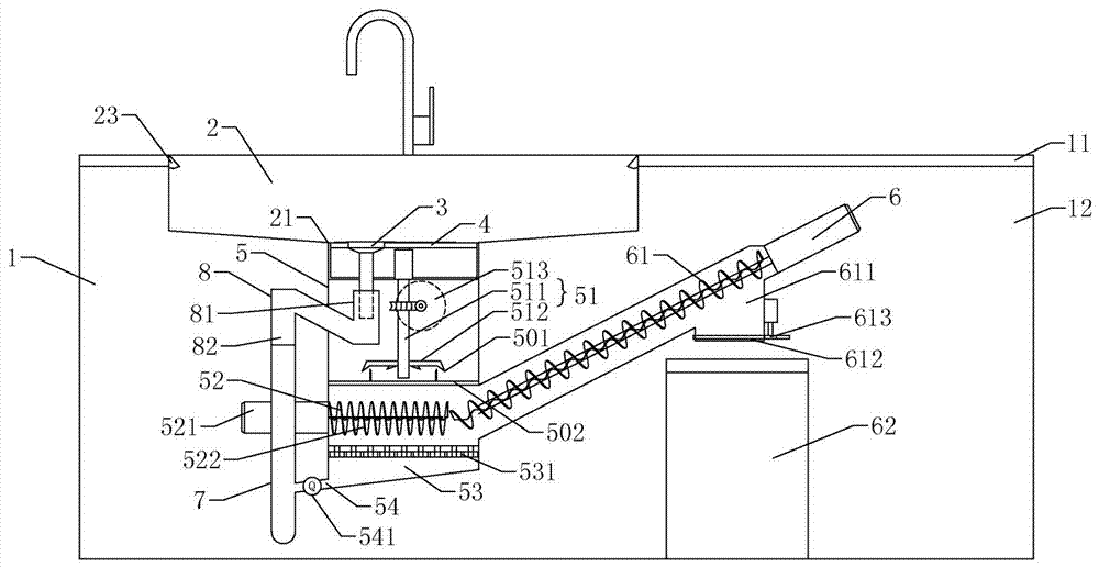
[0042] according to figure 1 As shown, an intelligent cabinet with a kitchen waste treatment system includes: a cabinet body 1, a sink body 2, a sewer plug 3 and a garbage discharge plug 4, and the cabinet body 1 is provided with a crushing box 5 and a solid collection mechanism 6 and downpipe 7;
[0043] The cabinet body 1 includes a top table top 11 and a cabinet body 12 below it. The sink body 2 is an under-counter tank. The discharge outlet 21 arranged at the bottom of the tank body 2, the top of the crushing box 5 is connected to the bottom of the waste discharge plug 4, the sewer plug 3 is connected to the sewer pipe 7 through the sewer elbow 8, and the sewer elbow 8 is arranged on the top of the sewer pipe 7;
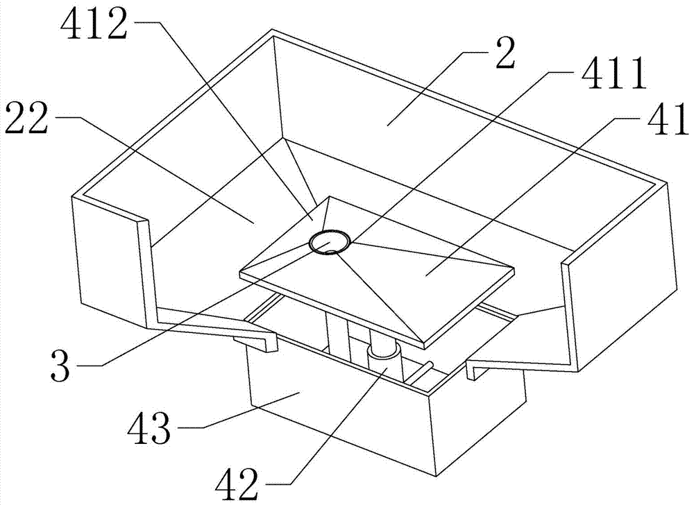
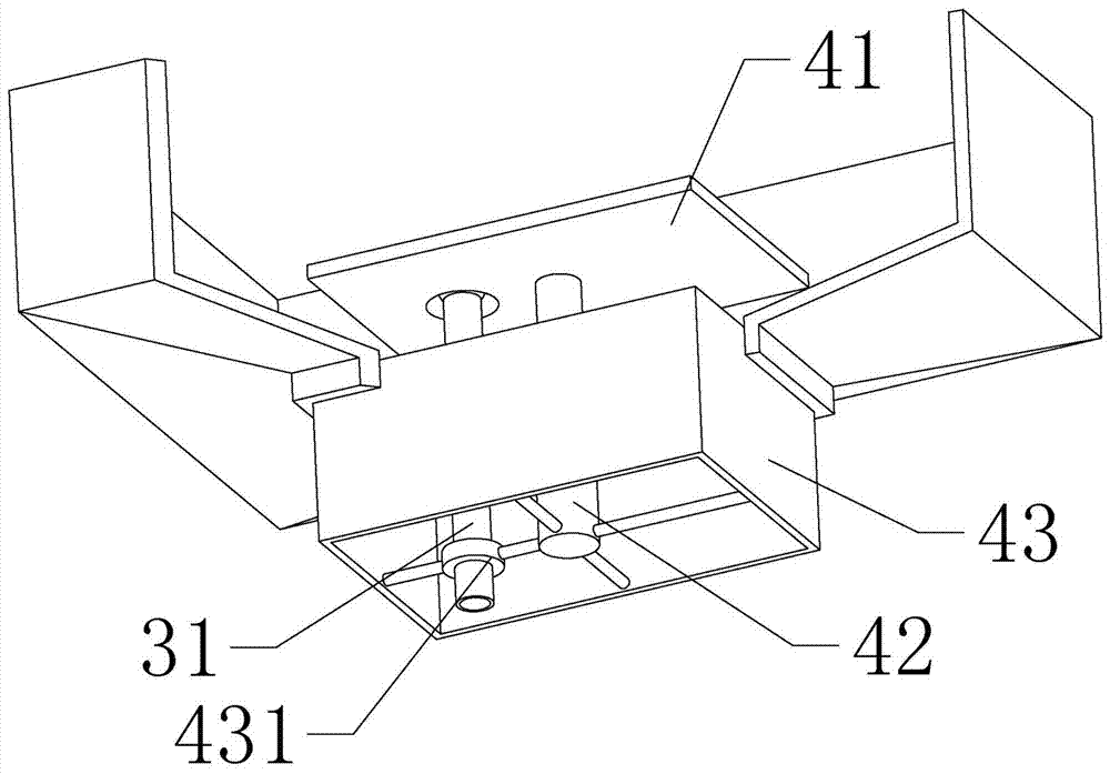
[0044] according to figure 2 , image 3As shown, the waste discharge plug 4 includes a lifting sealing plate 41, a bouncing tube 42 and an installation basket 43. The shape and size of the lifting sealing plate 41 match the discharge port 21. Between the lif...
Embodiment 2
[0059] The difference from the above-mentioned embodiment 1 is that, according to the figure 2 , image 3 As shown, the bottom of the water tank body 2 is provided with a tank body slope 22, and the slope direction of the tank body slope 22 is gradually reduced from the inner side wall of the water tank body 2 to the direction of the discharge port 21. The top of the lifting sealing plate 41 is provided with a sealing plate slope 412, The inclined direction of the sealing plate slope 412 is such that the height gradually decreases from the water hole 411 to the edge direction of the lifting sealing plate 41 .
[0060] In addition, a flushing nozzle 23 is arranged on the inner side wall of the tank body 2, and the flushing nozzle 23 is arranged on the inner side wall of each side of the tank body 2, and the straight line direction of the water outlet of each flushing nozzle 23 is in line with the discharge port 21. The circumscribed circle of the top view shape is tangent.
Embodiment 3
[0062] The difference from Embodiment 1 above is that the filter mechanism 53 includes a filter screen 531 and an inclined table below it, the pressure sensor is arranged above the filter screen 531, the lowest end of the inclined table is connected with the leachate drain pipe 54, and the filter screen 531 It is a multi-layer composite filter.
PUM
 Abstract
Description
Claims
Application Information
 - R&D
- Intellectual Property
- Life Sciences
- Materials
- Tech Scout
- Unparalleled Data Quality
- Higher Quality Content
- 60% Fewer Hallucinations
Browse by: Latest US Patents, China's latest patents, Technical Efficacy Thesaurus, Application Domain, Technology Topic, Popular Technical Reports.
© 2025 PatSnap. All rights reserved.Legal|Privacy policy|Modern Slavery Act Transparency Statement|Sitemap|About US| Contact US: help@patsnap.com


