
Hand-held object and hand shaking compensation method thereof

A hand-held and hand-mounted technology, applied in the direction of manipulators, program control, instruments, etc., can solve the problems of inflexible use, limited degrees of freedom, and no way to offset the rotation shake

Inactive Publication Date: 2017-11-24
BOE TECH GRP CO LTD
View PDF6 Cites 4 Cited by
  • Summary
  • Abstract
  • Description
  • Claims
  • Application Information

AI Technical Summary

Problems solved by technology

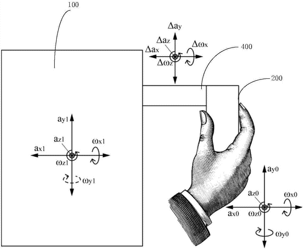
[0003] However, there are still some problems in the water cup or the water cup clamping structure provided in the prior art, for example: the existing water cup or the water cup clamping structure of the mechanical structure counteracts the shaking method with limited freedom of movement and inflexible use , some solutions still have the problem of not being able to distinguish between hand shake and normal movement; moreover, the existing methods and devices for unintentional shake cancellation are only for translational shake, and there is no way to offset rotational shake

Method used


Image

  • Hand-held object and hand shaking compensation method thereof
  • Hand-held object and hand shaking compensation method thereof
  • Hand-held object and hand shaking compensation method thereof

Examples


Embodiment 1

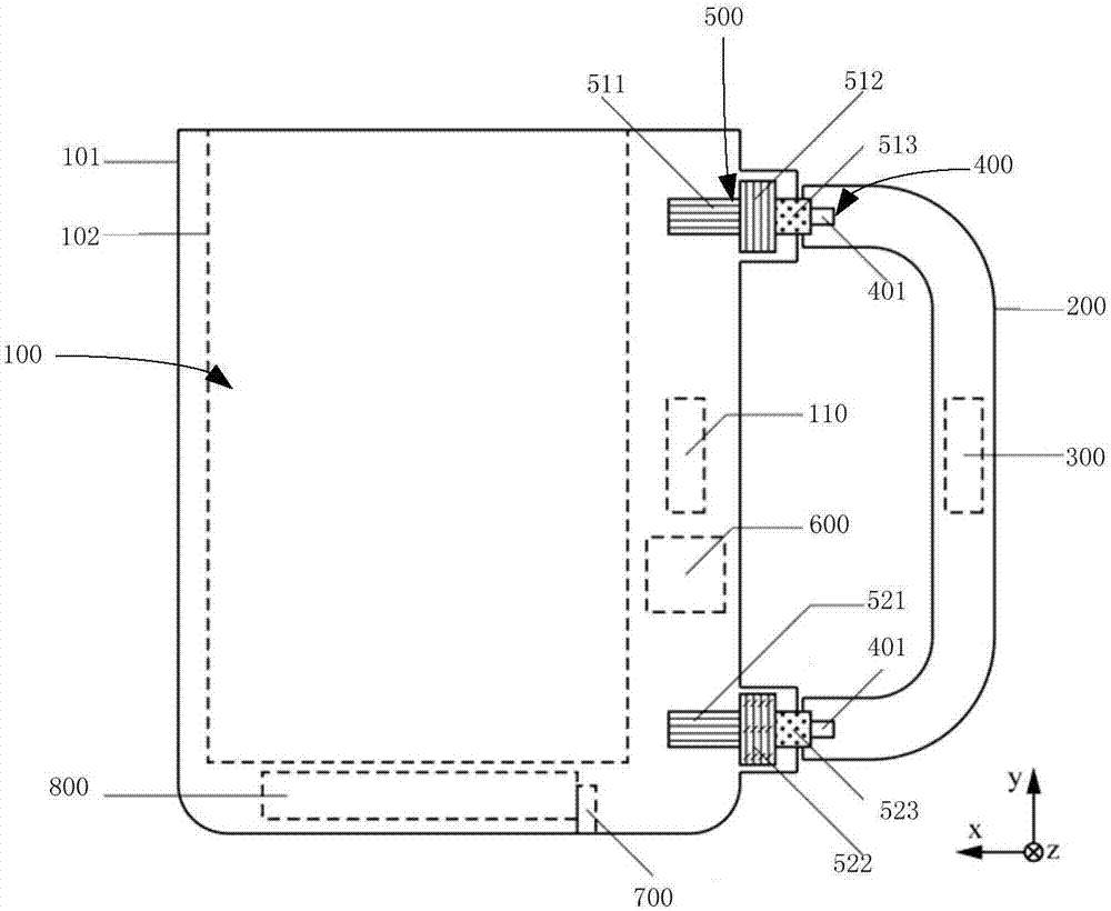
[0076] Such as figure 2 Shown is a schematic structural view of the first embodiment of the handheld object provided by the present invention.

[0077] In this example, if figure 2 As shown, the main part of the handle part 200 extends along the Y axis and has opposite first and second ends, and the first end and the second end of the handle part 200 are respectively connected to the functional main part 100 Connect through the movable connector 400;

[0078] The motion mechanism 500 includes:

[0079] The first motion assembly provided at the first end of the handle part 200, the first motion assembly includes: for controlling the movement of the function body part 100 relative to the first end of the handle part 200 on the X-axis The first X-axis moving part 511 that moves linearly in the direction; the first Y-axis that is used to control the first end of the functional body part 100 to move linearly in the Y-axis direction relative to the first end of the handle part ...

Embodiment 2

[0099] As shown in the figure, it is a schematic structural diagram of the second embodiment of the handheld object provided by the present invention.

[0100] In this example, if Figure 4 As shown, the main part of the handle part 200 extends along the Y axis, and has opposite first ends and second ends, and the first end of the handle part 200 is connected to the functional main part 100 through the flexible connection 400 is connected, and the second end is not connected to the functional body part 100;

[0101] The motion mechanism 500 includes:

[0102] a third X-axis direction moving part 531 for controlling the functional body part 100 to move linearly in the X-axis direction relative to the first end of the handle part 200;

[0103] a third Y-axis direction moving part 532 for controlling the functional body part 100 to move linearly in the Y-axis direction relative to the first end of the handle part 200;

[0104] A third Z-axis moving component 533 for controllin...


PUM


Abstract

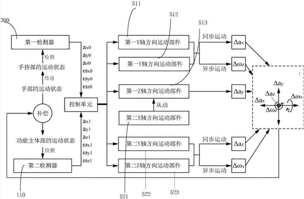
The invention provides a hand-held object and a hand shaking compensation method thereof. The hand-held object comprises a functional body part for a user to use, a hand-held part for the user to hold, a movable connecting piece through which the functional body part and the hand-held part are movably connected, a movement mechanism for driving the functional body part to move relative to the hand-held part, and a control unit, wherein the hand-held part is provided with a first detector for detecting the movement state of the hand-held part to acquire hand shaking information of the user; the movable connecting piece ensures that the functional body part can move relative to the hand-held part; the movement mechanism is connected with the functional body part; and the control unit is used for controlling the working state of the movement mechanism according to the hand shaking information, acquired by the first detector, of the user and driving the functional body part to perform compensating motion relative to the hand-held part, so that the position of the functional body part is kept in a preset position. The hand-held object can perform corresponding compensating motion according to the hand shaking state of a hand-shaking patient to eliminate the influence of hand shaking, and therefore, can be conveniently used by the hand shaking patient.

Description

technical field [0001] The invention relates to the technical field of daily necessities, in particular to a handheld object and a hand shake compensation method thereof. Background technique [0002] People with Parkinson's disease, elderly people with weak hands, and people with hand-shaking symptoms have difficulty using daily necessities such as drinking glasses. At present, for patients suffering from hand-shaking symptoms, there are also some water cups or water cup clamping structures, which can reduce the shaking of the water cup. [0003] However, there are still some problems in the water cup or the water cup clamping structure provided in the prior art, for example: the existing water cup or the water cup clamping structure of the mechanical structure counteracts the shaking method with limited freedom of movement and inflexible use However, some solutions still have the problem of not being able to distinguish between hand shaking and normal movement; moreover, ...

Claims


Application Information

Patent Timeline
Patent Type & Authority Applications(China)
IPC IPC(8): B25J11/00B25J13/08A61B5/11
CPCA61B5/1101A61B5/1121B25J11/009B25J13/08A47G19/22A61B5/6887A61B2560/0431A47G2200/046B25J13/088G05B2219/41116G05B19/404
Inventor 刘成
Owner BOE TECH GRP CO LTD
Learn More