Concrete preparation machinery for water conservancy construction

A concrete and mechanical technology, applied in the field of concrete preparation machinery, can solve the problems of different impact force of materials, large manpower consumption, interference in weighing process, etc., and achieve the effect of uniform impact force and accurate weighing

Inactive Publication Date: 2017-11-24
刘冬峰
View PDF0 Cites 1 Cited by
  • Summary
  • Abstract
  • Description
  • Claims
  • Application Information

AI Technical Summary

Problems solved by technology

In the prior art, the sand and stones that are sieved out are inaccurately weighed when they are prepared on site, and the design of concrete mix ratio is a very important task in concrete engineering, which directly affects the smooth construction of concrete and the quality of concrete engineering. and the cost of concrete works
There is an error between the actual configuration of concrete and the preset concrete mix ratio, which is a common problem in existing engineering construction. For projects with relatively high requirements, only raw materials that have been weighed and packaged can be purchased, resulting in high construction costs
[0003] In order to reduce costs, there are currently projects that adopt on-site weighing and weighing for concrete configuration. Usually, it is conveyed through the material belt and transported to a small material pan for weighing. However, when the sand and gravel materials fall to the material pan, it will cause a downward impact on the material pan. , and the impact force of materials with different densities is also different, which will interfere with the weighing process
[0004] In addition, the specifications of bulk sand and gravel are not uniform. During the configuration process, it is first necessary to sieve sand of different thicknesses according to the preset ratio, so as to be used for different purposes.
As a result, the existing configuration method is complicated to operate and consumes a lot of manpower

Method used


Image

  • Concrete preparation machinery for water conservancy construction
  • Concrete preparation machinery for water conservancy construction
  • Concrete preparation machinery for water conservancy construction

Examples


Embodiment 1

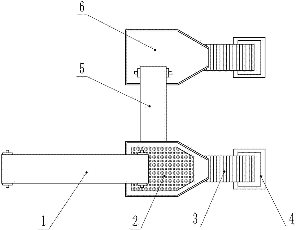
[0023] In embodiment 1 such as figure 1 , 2 , 3, the present embodiment includes a conveyor belt, a frame body, a vibrating screen 2, a lower hopper 6, a bucket conveyor 3 and a weighing assembly 4. In order to facilitate the display of the internal structure, the frame structure has been partially omitted in the figure, and only the part connected to other structures is drawn, that is, the straight line with hatching in the figure (except for the section line). The frame structure is used to support, connect and fix other structures. Since the specific structure of the frame is determined by the position and size of other structures and has no impact on the working principle of the present invention, its specific structure will not be repeated.

[0024] The conveyor belts include a No. 1 conveyor belt 1 and a No. 2 conveyor belt 5. The end of the No. 1 conveyor belt 1 is located above the vibrating screen 2, and is fed into the vibrating screen 2 through the No. 1 conveyor b...

Embodiment 2

[0035] In embodiment 2, such as Figure 4 , 5 As shown, the present embodiment includes a conveyor belt, a frame body, a vibrating screen 2, a lower hopper 6, a bucket conveyor 3 and a weighing assembly 4. Wherein the conveyor belt, the vibrating screen 2, the lower hopper 6, and the bucket conveyor 3 are the same in structure and connection relationship as in Embodiment 1, and will not be repeated in this embodiment. The frame structure is adaptively changed according to the change of the structure of the weighing assembly 4 . The difference between this embodiment and Embodiment 1 mainly lies in the change of the weighing assembly 4 .

[0036] Described installation assembly 4 comprises No. 1 set pan frame 38, No. 1 crossbeam 28, No. 2 crossbeam 24 and dolly 27, and described No. 1 set pan frame 38 is fixed on the frame body (or it can be said that frame body a part of it), placed obliquely, the front is high and the back is low, the No. 1 tray rack 38 is used to place th...

Embodiment 3

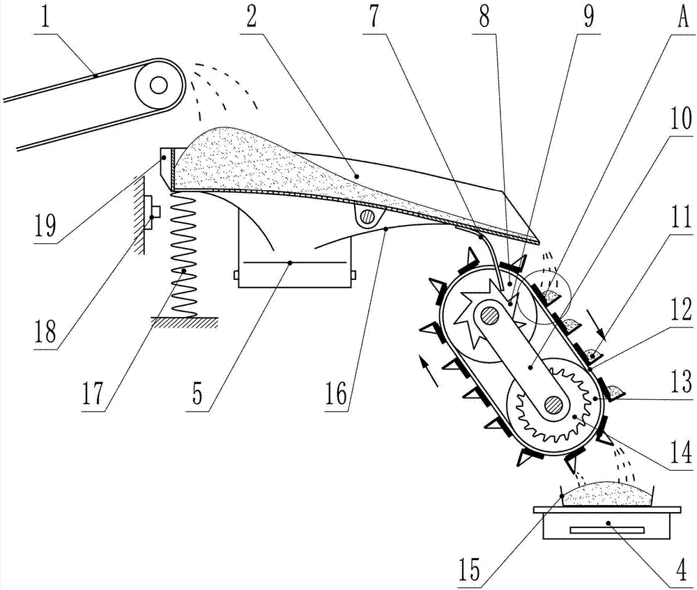
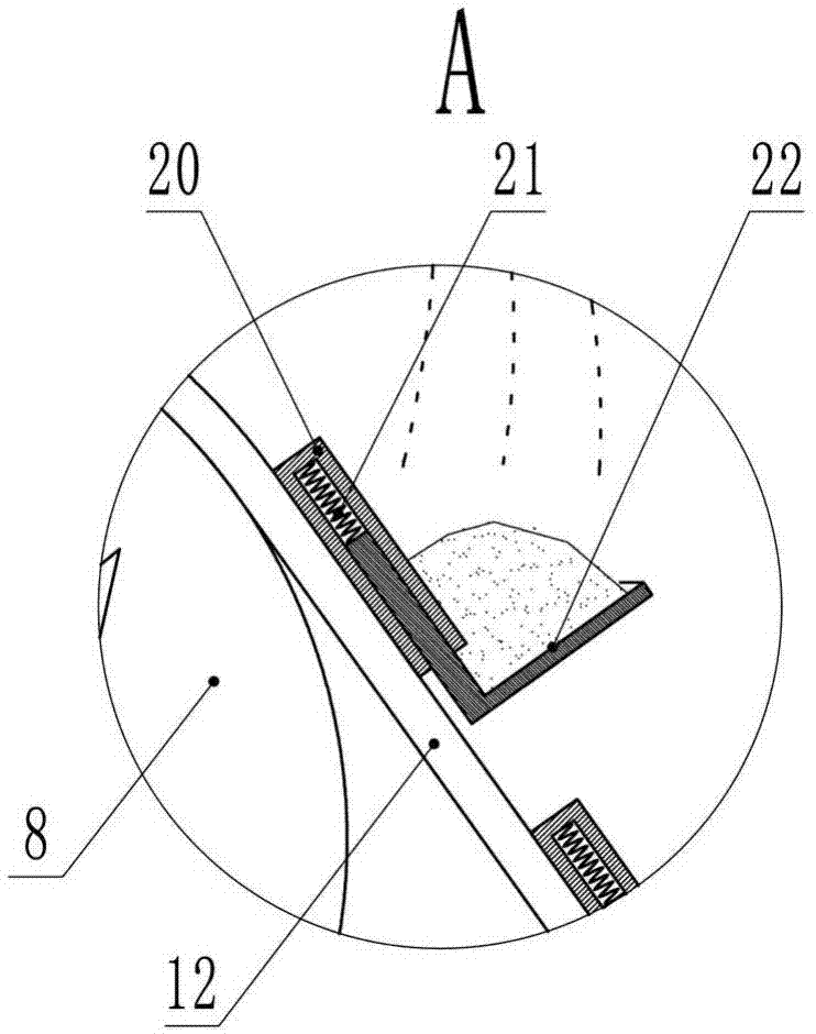
[0042] In Embodiment 3, this embodiment is an ore feeding device. Such as Figure 6 , 7 As shown, the present embodiment includes a conveyor belt, a crusher 61 , a frame body, a vibrating screen 2 , a bucket conveyor 3 and a weighing assembly 4 . For ease of description, the outlet direction of the vibrating screen 2 is set as the front, and the opposite direction is the back.

[0043] The conveyor belts include a feed conveyor belt 60 and a return conveyor belt 62 . The head end of the feeding conveyor belt 60 is located at the stockyard, and its feeding method can be manual feeding or mechanical feeding. The end of the feeding conveyor belt 60 is located above the rear end of the vibrating screen 2 . The head end of the return conveyor belt 62 is located below the outlet of the vibrating screen 2, the end of the return conveyor belt 62 is located at the feed inlet of the crusher 61, and the discharge port of the crusher 61 is located at the feeding conveyor belt 60. In ...


PUM


Abstract

The invention discloses a concrete preparation machine for water conservancy construction, which belongs to the field of engineering construction machinery, and is characterized in that it includes a conveyor belt, a frame body, a vibrating screen, a lower hopper, a bucket conveyor and a weighing assembly; the conveying The belt includes No. 1 conveyor belt and No. 2 conveyor belt; a group of bucket conveyors and a weighing assembly are respectively provided under the vibrating screen and the lower hopper; supporting springs are respectively provided under the vibrating screen and the front end of the lower hopper; The bottom of the sieve is provided with a material guide plate; the bucket conveyor is respectively located below the opening of the vibrating screen and the lower hopper, including a traction chain, a small hopper, a head wheel, a tail wheel, a ratchet and a connecting plate; the head wheel and The sides of the tail wheel are respectively fixedly connected with No. 1 ratchet and No. 2 ratchet, wherein a spring leaf is fixedly connected with each of the vibrating screen and the lower hopper; the weighing assembly includes a weighing device. Compared with the prior art, the utility model has the characteristics of convenient and accurate weighing.

Description

technical field [0001] The invention relates to an engineering construction machine, in particular to a concrete preparation machine suitable for water conservancy construction. Background technique [0002] Concrete is the most important building material, and engineering designers need to choose different concrete ratio designs according to the project structure, the amount of steel reinforcement, construction methods and other requirements. The so-called concrete construction mix ratio refers to the proportional relationship between the various constituent materials in concrete. The constituent materials include cementitious materials, cement, sand, stones and water. In the prior art, the sand and stones that are sieved out are inaccurately weighed when they are prepared on site, and the design of concrete mix ratio is a very important task in concrete engineering, which directly affects the smooth construction of concrete and the quality of concrete engineering. and the...

Claims


Application Information

Patent Timeline
Patent Type & Authority Applications(China)
IPC IPC(8): B28C7/10B28C7/04B07B1/28B07B1/42B07B1/46
CPCB28C7/10B07B1/28B07B1/42B07B1/4609B28C7/044
Inventor 刘冬峰
Owner 刘冬峰
Why Eureka
Try Eureka