[0015] The technical solutions in the embodiments of the present invention will be clearly and completely described below in conjunction with the accompanying drawings in the embodiments of the present invention. Obviously, the described embodiments are only a part of the embodiments of the present invention, rather than all the embodiments. Based on the embodiments of the present invention, all other embodiments obtained by those of ordinary skill in the art without creative work shall fall within the protection scope of the present invention.
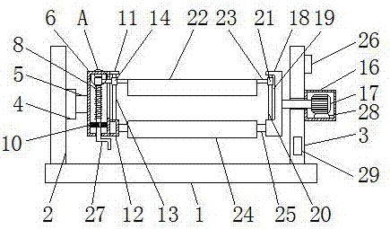
[0016] See Figure 1-2 , A fabric winding device for textile machinery, comprising a base 1. The left and right sides of the top of the base 1 are respectively fixedly connected with a first fixing plate 2 and a second fixing plate 3, and the bottom of the front of the second fixing plate 3 is provided with The label 29, the label 29 and the second fixing plate 3 are fixedly connected by a fixing member. The setting of the label 29 facilitates the recording and classification of fabrics and is convenient for sorting. The right side of the first fixing plate 2 is fixedly connected with the first fixing shaft 4 , The shaft 5 on the right side of the first fixed shaft 4 is movably connected with a rotating shaft 5, the right end of the rotating shaft 5 is fixedly connected with a fixing frame 6, the top of the inner cavity of the fixing frame 6 is fixedly connected with a second fixing shaft 7, and a second fixing shaft 7. A threaded rod 8 is movably connected to the axis of the bottom. The surface of the threaded rod 8 is provided with an external thread. The inside of the threaded sleeve 9 is provided with an internal thread for use with the external thread. The surface of one end of the threaded rod 8 is sleeved with a threaded sleeve 9 , The end of the threaded rod 8 away from the second fixed shaft 7 is fixedly connected to the gear 10, and the shaft center at the bottom of the gear 10 is fixedly connected to a handle 27. The end of the handle 27 away from the gear 10 penetrates the fixing frame 6 and extends to the outside of the fixing frame 6. By setting the handle 27, the gear 10 can be driven to rotate and the threaded rod 8 can be adjusted. The top of the right side of the fixing frame 6 is fixedly connected with the connecting plate 11, and the bottom of the right side of the fixing frame 6 is fixedly connected with the connecting frame 12, and the connecting plate A first sliding rod 13 is fixedly connected between 11 and the connecting frame 12. The surface of one end of the first sliding rod 13 is sleeved with a first sliding sleeve 14, and the left side of the first sliding sleeve 14 is fixedly connected with a moving rod 15. The left end of 15 penetrates the fixing frame 6 and extends to the inside of the fixing frame 6 to be fixedly connected to the right side of the threaded sleeve 9. The right side of the second fixing plate 3 is fixedly connected to a motor box 16, and the motor box 16 is provided with a motor 17. The bottom of the motor 17 is fixedly connected with a shock-absorbing pad 28, and the bottom of the shock-absorbing pad 28 is fixedly connected with the bottom of the inner cavity of the motor box 16. The setting of the shock-absorbing pad 28 can protect the motor 17 and prolong the service life of the motor 17 , The output shaft of the motor 17 sequentially penetrates the motor box 16 and the second fixing plate 3 and extends to the outside of the second fixing plate 3 to be fixedly connected with a connecting block 18. The left side of the connecting block 18 is provided with a groove 19. A second sliding rod 20 is fixedly connected to the inside, and a second sliding sleeve 21 is sleeved on the surface of one end of the second sliding rod 20. Through the arrangement of the second sliding rod 20 and the second sliding sleeve 21, the first winding roller 22 can be added For the stability of movement, a first winding roller 22 is arranged between the first sliding sleeve 14 and the second sliding sleeve 21. Both sides of the first winding roller 22 are fixedly connected with a first connecting rod 23, and the first connecting rod 23 are respectively fixedly connected with the first sliding sleeve 14 and the second sliding sleeve 21, the bottom of the first winding roller 22 is provided with a second winding roller 24, and both sides of the second winding roller 24 are fixedly connected with a second connection The rod 25 and the second connecting rod 25 are respectively fixedly connected to the connecting frame 12 and the connecting block 18. The top right side of the second fixing plate 3 is fixedly connected to the controller 26, which is electrically connected to the motor 17, through the gear 10 and The setting of the threaded rod 8 can drive the threaded sleeve 9 to move, and the threaded sleeve 9 While moving, the moving rod 15 drives the first sliding sleeve 14 to slide on the surface of the first sliding rod 13, and the setting of the first connecting rod 23 drives the first winding roller 22 to move. Adjusting the width between the winding rollers 24 also solves the problem that the winding rollers are all fixed in size, and the width cannot be adjusted, which is inconvenient for people to use.
[0017] When in use, the motor 17 is started by the controller 26, and the motor 17 drives the connecting block 18 to rotate, and at the same time drives the first winding roller 22 and the second winding roller 24 to rotate through the fixed frame 6, the rotating shaft 5 and the first fixed shaft 4. When the width of the winding roller needs to be adjusted, turn the gear 10 through the handle 27 to drive the threaded rod 8 to rotate, and at the same time the threaded sleeve 9 moves, and the first sliding sleeve 14 is driven by the moving rod 15 A sliding rod 13 slides on the surface to drive the first winding roller 22 to move, and at the same time, the second sliding sleeve 21 is driven to slide on the surface of the second sliding rod 20 through the first connecting rod 23, and the first winding roller 22 and the second winding The width between the rollers 24 is adjusted.
[0018] To sum up: the fabric winding device for textile machinery solves the problem of winding up through the cooperation of the first fixed shaft 4, the rotating shaft 5, the fixing frame 6, the second fixed shaft 7, the threaded rod 8, the threaded sleeve 9 and the gear 10. The rolls are of fixed size, and the width cannot be adjusted, which is inconvenient for people to use.
[0019] Although the embodiments of the present invention have been shown and described, those of ordinary skill in the art can understand that various changes, modifications, and substitutions can be made to these embodiments without departing from the principle and spirit of the present invention. And variations, the scope of the present invention is defined by the appended claims and their equivalents.