
Air conditioning unit

A technology for air conditioning units and air conditioners, which is applied to air conditioning systems, refrigerators, refrigeration components, etc., can solve the problems that air conditioners cannot supply air from multiple angles and all directions, ensure normal rotation and work, and solve pipeline knots. Effect

Active Publication Date: 2017-11-24
QINGDAO HAIER AIR CONDITIONING ELECTRONICS CO LTD +1
View PDF7 Cites 0 Cited by
  • Summary
  • Abstract
  • Description
  • Claims
  • Application Information

AI Technical Summary

Problems solved by technology

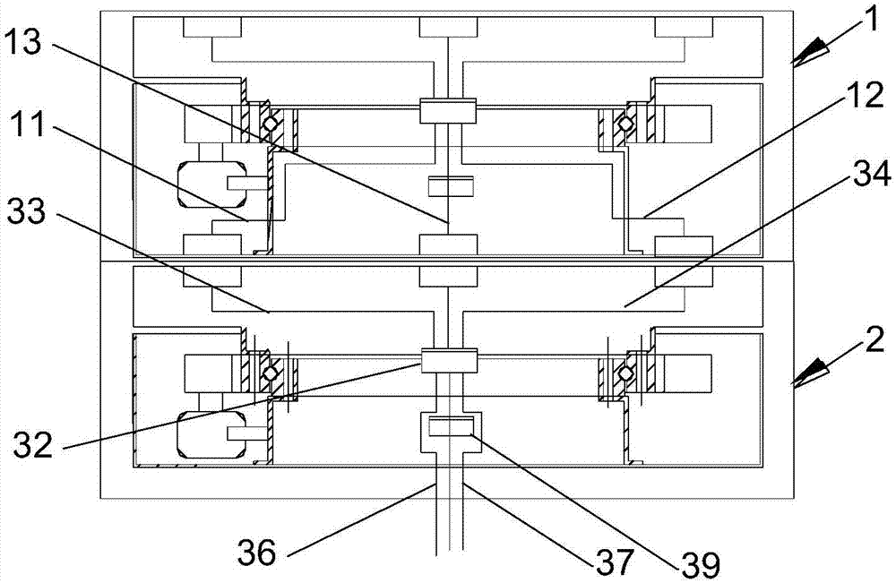
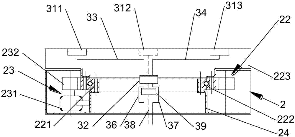
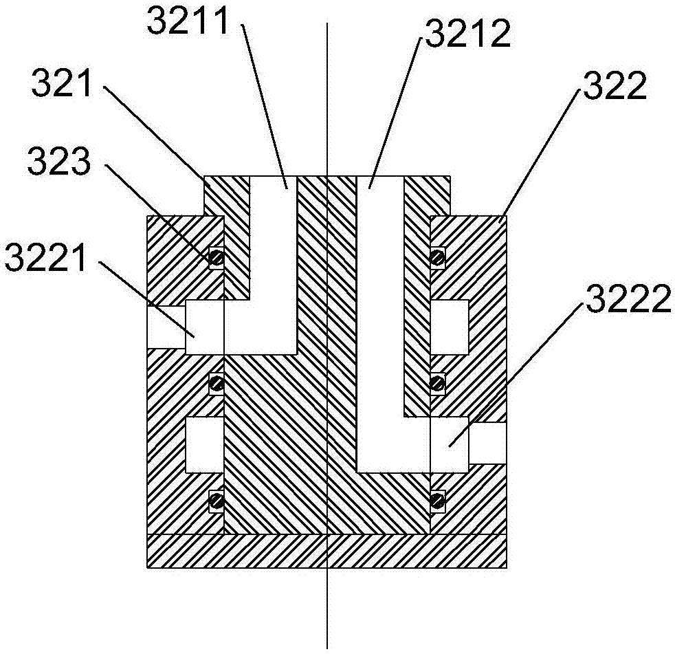
[0006] In order to solve the above problems in the prior art, that is, in order to solve the problem that the existing air conditioner cannot supply air from multiple angles and all directions, the present invention provides an air conditioner unit, which includes: a first air conditioner, the first air conditioner An air conditioner includes a first refrigerant connecting pipe and a first condensed water connecting pipe; a support device, the supporting device includes a second refrigerant connecting pipe and a second condensed water connecting pipe; a rotating mechanism, the first air conditioner passes through the The rotating mechanism is connected with the support device, so that the air conditioner can rotate relative to the support device; the pipeline swivel joint is arranged between the rotation mechanism and the support device, and the pipeline swivel joint includes a Relatively rotating first end and second end, the first end of the pipeline rotary joint is connected to the first refrigerant connection pipe and / or the first condensate water connection pipe, and the second end of the pipeline rotary joint is connected to The second refrigerant connecting pipe and / or the second condensate connecting pipe

Method used


Image

  • Air conditioning unit
  • Air conditioning unit
  • Air conditioning unit

Examples


Embodiment Construction

[0027] Preferred embodiments of the present invention are described below with reference to the accompanying drawings. Those skilled in the art should understand that these embodiments are only used to explain the technical principles of the present invention, and are not intended to limit the protection scope of the present invention.

[0028] It should be noted that, in the description of the present invention, terms such as "upper", "lower", "inner", "outer" and other indicated directions or positional relationships are based on the directions or positional relationships shown in the accompanying drawings, which It is for the convenience of description only, and does not indicate or imply that the device or element must have a specific orientation, be constructed and operate in a specific orientation, and thus should not be construed as limiting the present invention. In addition, the terms "first", "second", and "third" are used for descriptive purposes only, and should no...


PUM


Abstract

The invention belongs to the technical field of air conditioners, and particularly provides an air conditioning unit. The air conditioning unit aims to solve the problem that multi-angle and all-round blowing of an existing air conditioner can not be achieved. The air conditioning unit comprises a first air conditioner, a supporting device, a rotating mechanism and a pipeline swivel joint, wherein the first air conditioner comprises a first refrigerant connecting pipe and a first condensate water connecting pipe, and the supporting device comprises a second refrigerant connecting pipe and a second condensate water connecting pipe; and the first air conditioner is connected with the supporting device through the rotating mechanism, and the air conditioner can rotate relative to the supporting device; and the pipeline swivel joint is arranged between the rotating mechanism and the supporting device, the pipeline swivel joint comprises a first end and a second end, wherein the first end and the second end can relatively rotate, the first end of the pipeline swivel joint is connected with the first refrigerant connecting pipe and / or the first condensate water connecting pipe, and the second end of the pipeline swivel joint is connected with second refrigerant connecting pipe and / or the second condensate water connecting pipe. According to the air conditioning unit, under the situation that the above technical characteristics are adopted, multi-angle blowing of the air conditioner can be achieved.

Description

technical field [0001] The invention belongs to the technical field of air conditioners, and specifically provides an air conditioner unit. Background technique [0002] An air conditioner is a device that processes air humidity, temperature, purity, and airflow velocity. Air conditioners are used in many aspects, such as people's homes, vehicles, and working environments, which improve people's living and working environments and greatly increase people's comfort. [0003] However, once the air conditioner is installed, the pipelines and circuits of the air conditioner are fixed, and the air conditioner can only rely on the up, down, left, and right rotation of the air deflector to expand the air supply area. The limitation of road, line and installation position makes it difficult for the air conditioner to rotate. Therefore, the existing air conditioner cannot supply air from multiple angles and in all directions. [0004] In order to solve the problem that the air cond...

Claims


Application Information

Patent Timeline
IPC IPC(8): F24F1/00F25B41/00F24F13/22F24F13/32F24F11/02F25B41/40
CPCF24F1/00F24F13/222F24F13/32F25B41/00
Inventor 刘新波王春玉赵心蕾董德智国德防冯康黄尧
Owner QINGDAO HAIER AIR CONDITIONING ELECTRONICS CO LTD
Learn More