Sliding surface pull-type landslide model test device

A landslide model test and sliding surface pulling technology, which is applied in soil material testing, material inspection, etc., can solve the problems of overall instability and damage, and achieve the effect of simple operation, simple overall structure, and clear layout

Active Publication Date: 2017-11-24
SOUTHWEST JIAOTONG UNIV
View PDF8 Cites 6 Cited by
  • Summary
  • Abstract
  • Description
  • Claims
  • Application Information

AI Technical Summary

Problems solved by technology

Earthquakes often cause overall instability and damage, and it is difficult to simulate gradual damage

Method used


Image

  • Sliding surface pull-type landslide model test device
  • Sliding surface pull-type landslide model test device
  • Sliding surface pull-type landslide model test device

Examples


Embodiment 1

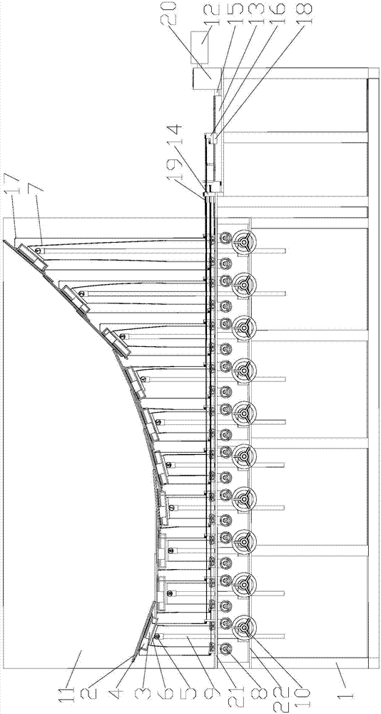
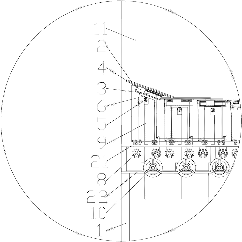
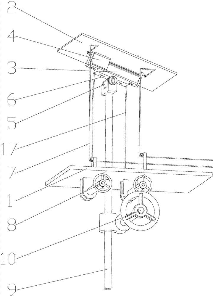
[0027] like figure 1 , figure 2 , image 3 and Figure 4 As shown, a sliding surface pulling type landslide model test device includes an outer frame 1, and a lifting unit and a power module arranged on the outer frame 1; And lifting mechanism, guide rail slide block comprises guide rail 3 and the slide block 4 that moves in guide rail 3, and the upper end of slide block 4 is fixedly connected with described slide plate 2; The connecting plate 6, the connecting plate 6 is fixedly connected to the guide rail 3; the adjustment mechanism includes the pipelines 7 respectively arranged on the connecting plates 6 on both sides of the hinge rod 5, each pipeline 7 is connected with a movable pulley below, and the movable pulley is connected There is an adjustment handwheel 8; the lifting mechanism includes a cooperatingly connected worm wheel and a worm 9, and the worm wheel is provided with a lifting handwheel 10 for adjustment; the hinged rod 5 is hinged to the upper end of the ...

Embodiment 2

[0033] This embodiment is a further improvement on the basis of Embodiment 1, and the difference from Embodiment 1 is:

[0034] Preferably, a protective gearbox 20 is arranged outside the reduction gear set. Setting the gear set in the gearbox can prevent the gear set from being touched by mistake, resulting in structural damage or affecting the accuracy. Setting the gear set in the gearbox can also prevent people from being injured by mistake and improve safety.

[0035] Preferably, a dust shield 21 is provided below the slide plate 2, a lifting mechanism mounting plate 22 is arranged below the dust shield 21, the transparent plate 11 is arranged on the dust shield 21, and the dust shield 21 and the lifting mechanism mounting plate 22 are all fixed on the outer frame 1. The use of the dust shield can effectively reduce the impact of dust generated during the experiment on the lifting mechanism. The lifting mechanism mounting plate can facilitate the fixing of the lifting mec...


PUM


Abstract

The invention discloses a sliding surface pull-type landslide model test device. The sliding surface pull-type landslide model test device comprises an outer frame, a lifting unit and a power module, wherein the lifting unit and the power module are arranged on the outer frame. The lifting unit comprises a sliding plate, a guide rail sliding block, a rotary support, an adjusting mechanism and a lifting mechanism. The guide rail sliding block comprises a guide rail and a sliding block. The rotary support comprises a hinge rod and a connecting plate arranged on the hinge rod. The adjusting mechanism comprises pipes arranged in two sides of the hinge rod, movable pulleys are connected to the lower parts of the pipes and the movable pulleys are connected to adjusting hand wheels. The lifting mechanism comprises a worm gear and a worm fitting to and connected to the worm gear. The worm gear is provided with a lifting hand wheel. The power module comprises a servo motor, a slide rail and a speed reduction gear set which are arranged on the outer frame. The servo motor is connected to a screw guide rail through the speed reduction gear set. The screw guide rail is connected to a power distribution plate through threads. The two ends of the sliding plate are provided with pull ropes. The pull ropes pass through a pipe joint mounting plate. The pull ropes are provided with pull force sensors. The sliding surface pull-type landslide model test device realizes a model test in various directions and improves safety.

Description

technical field [0001] The invention relates to the technical field of landslide model test devices, in particular to a sliding surface pulling type landslide model test device. Background technique [0002] my country's mountains and hills account for about 70% of the country's land area, and it is a country with serious landslide hazards in the world. With the development of infrastructure, a large number of excavated hillsides formed by the construction of reservoirs, power stations, roads and factories in mountainous areas may produce new landslides or lead to the resurrection of old landslides. Therefore, my country is one of the countries with very serious geological disasters. The losses and threats brought by people are also huge, sometimes immeasurable. Landslide is the sliding phenomenon of slope rock and soil mass along the through shear failure surface. The mechanism of the landslide is that the shear stress on a slip plane exceeds the shear strength of the plan...

Claims


Application Information

Patent Timeline
Patent Type & Authority Applications(China)
IPC IPC(8): G01N33/24
CPCG01N33/24Y02A10/23
Inventor 杨涛孙立娟康健蔡佳豪王泽华
Owner SOUTHWEST JIAOTONG UNIV
Why Eureka
Try Eureka