
Eureka
For R&D, Eureka makes reading and utilizing patents & technical documents easy.
Eureka AIR
Designed for self-driven R&D workflows. Generate viable solutions, solve complex R&D challenges, empower your innovation with AI.

Eureka Materials
Designed for material experts only. Revolutionize your material R&D, from search, analyze, to developing new materials.

TechResearch
Generate reliable direction feasibility study reports for your R&D in just a few steps.

TechSeek
Discover and master advanced knowledge NOW. Basics, ideas, possibilities, all at once.

TechMind
As an expert in R&D Theories, TechMind can generates customized viable solutions instantly.

TechRisk
Analyze your overall solution with one click, know your potential R&D risks in advance.

TechMonitor
Get weekly tech updates, stay abreast of the latest tech innovations and key insights.
Remote-control switch cabinet convenient to manage
A switch cabinet and cabinet body technology, which is applied in the field of remote control switch cabinets, can solve problems such as troublesome installation and disassembly, and achieve the effect of convenient and quick adjustment
- Summary
- Abstract
- Description
- Claims
- Application Information
AI Technical Summary
Problems solved by technology
Method used
Image

Examples
Embodiment 1
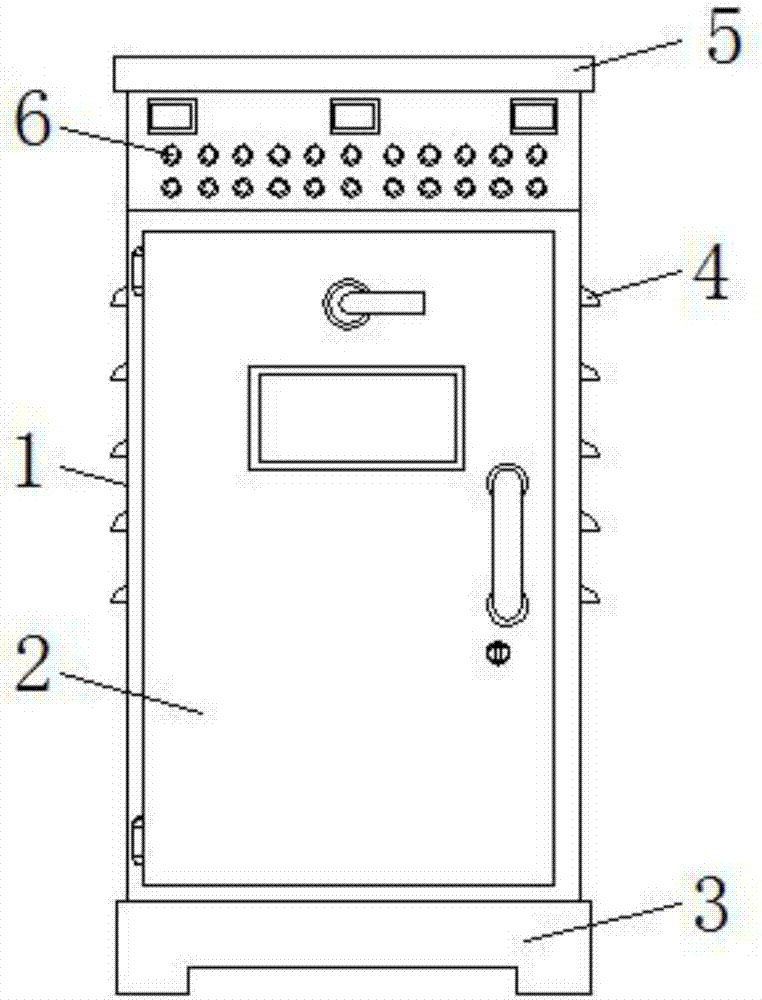
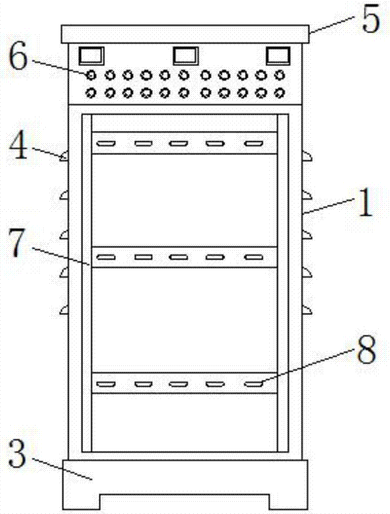
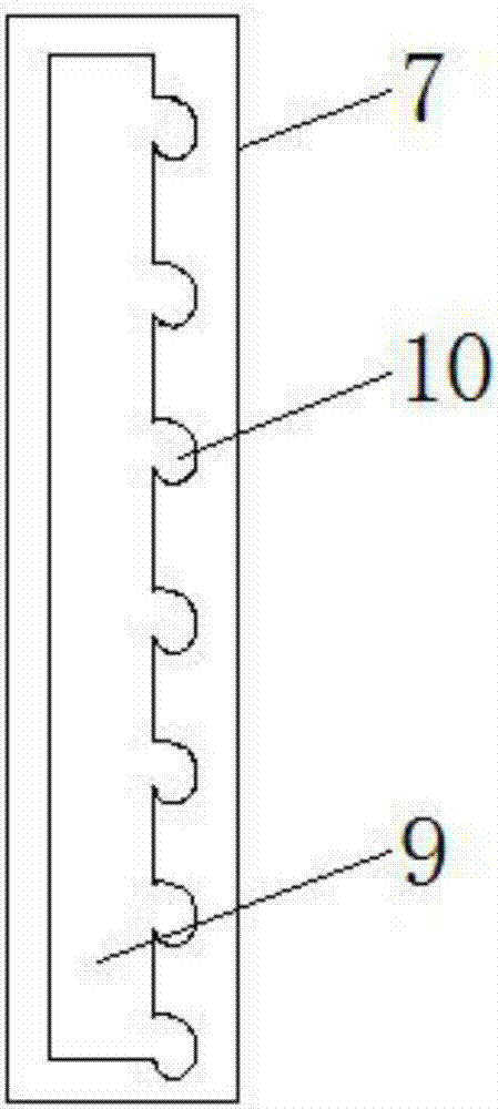
[0023] see figure 1 , figure 2 , image 3 and Figure 4 , the present invention provides a technical solution: a remote control switch cabinet that is easy to manage, including a cabinet body 1 and a connecting rod 12, the bottom of the cabinet body 1 is provided with a bottom plate 3, and the front surface of the cabinet body 1 is provided with a dodge door 2, The front surface of the cabinet 1 is provided with an indicator light 6 close to the top of the dodge door 2, the left and right surfaces of the cabinet 1 are provided with ventilation grilles 4, the top surface of the cabinet 1 is provided with a top plate 5, and the left and right inner walls of the cabinet 1 are A mounting rod 7 is provided, and a chute 9 is arranged on the surface of the mounting rod 7 away from the ventilation grille 4. One side of the chute 9 is provided with a fixing hole 10, and a support rod 8 is provided at the junction of the two mounting rods 7, and the bracket The two ends of the rod 8...
Embodiment 2
[0032] see figure 1 , figure 2 , Figure 5 and Figure 6 , the present invention provides a technical solution: a remote control switch cabinet that is easy to manage, including a cabinet body 1 and a connecting rod 12, the bottom of the cabinet body 1 is provided with a bottom plate 3, and the front surface of the cabinet body 1 is provided with a dodge door 2, The front surface of the cabinet 1 is provided with an indicator light 6 close to the top of the dodge door 2, the left and right surfaces of the cabinet 1 are provided with ventilation grilles 4, the top surface of the cabinet 1 is provided with a top plate 5, and the left and right inner walls of the cabinet 1 are A mounting rod 7 is provided, and a chute 9 is provided on the surface of the mounting rod 7 away from the ventilation grille 4, and a restricting hole 13 is provided on the outer surface of the chute 9, and a bracket rod 8 is provided at the joint of the two mounting rods 7, The two ends of support bar...
PUM
 Abstract
Description
Claims
Application Information
 - R&D Engineer
- R&D Manager
- IP Professional
- Industry Leading Data Capabilities
- Powerful AI technology
- Patent DNA Extraction
Browse by: Latest US Patents, China's latest patents, Technical Efficacy Thesaurus, Application Domain, Technology Topic, Popular Technical Reports.
© 2024 PatSnap. All rights reserved.Legal|Privacy policy|Modern Slavery Act Transparency Statement|Sitemap|About US| Contact US: help@patsnap.com