Swinging type rotation gas claw device

A rotary air claw and swinging technology, applied in the field of manipulators, can solve the problems of small application range, inability to install and use, and large limitations, and achieve the effect of large application range, small occupied space, and small rotating space

Pending Publication Date: 2017-11-28
宁波开浦智能科技有限公司
View PDF9 Cites 6 Cited by
  • Summary
  • Abstract
  • Description
  • Claims
  • Application Information

AI Technical Summary

Problems solved by technology

[0003] At present, the most widely used loading and unloading device in mechanical cutting processing automation equipment is the rotary air claw device. The rotary cylinder is fixed on the inclined side of the rotary frame. The first air claw and the second air claw are respectively installed on the two right-angled sides of the rotary frame. An adjustment block that moves longitudinally on the side, the second air claw is installed on the adjustment block, the rotary cylinder is pierced with an inherent horizontal adjustment shaft, one end of the horizontal adjustment shaft is inserted on the rotating frame and the rotating frame can move radially along the horizontal adjustment shaft, With this air claw structure, each air claw can be switched to the position of the other air claw during the alternate conversion process of the two air claws, and the positioning is quite accurate, but at the same time there are the following technical problems. In this rotating air claw structure, due to The volume of the right-angled triangular-shaped rotating frame is large, resulting in a large structure of the entire rotating air gripper. In addition, although the two air grippers are perpendicular to each other, the two air grippers are inclined relative to the rotation plane of the rotating seat. In this way, the entire rotating air gripper The rotary air gripper rotates in a three-dimensional space, and it requires a large rotating space. After the bar is installed, the required space is even larger. Therefore, it cannot be installed and used in some narrow spaces, resulting in its limitations. large, small

Method used


Image

  • Swinging type rotation gas claw device
  • Swinging type rotation gas claw device
  • Swinging type rotation gas claw device

Examples


Embodiment 1

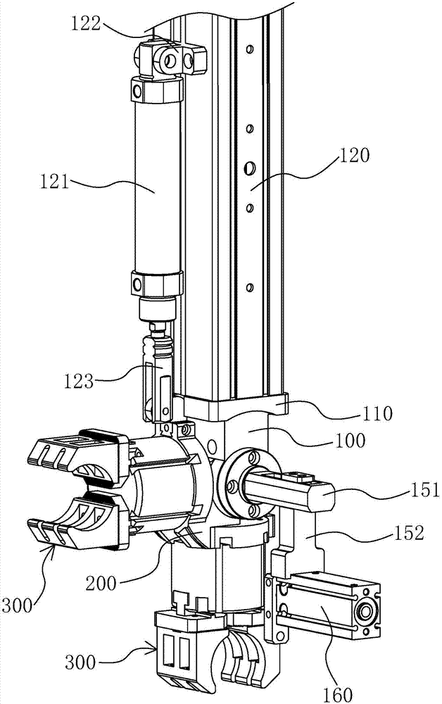
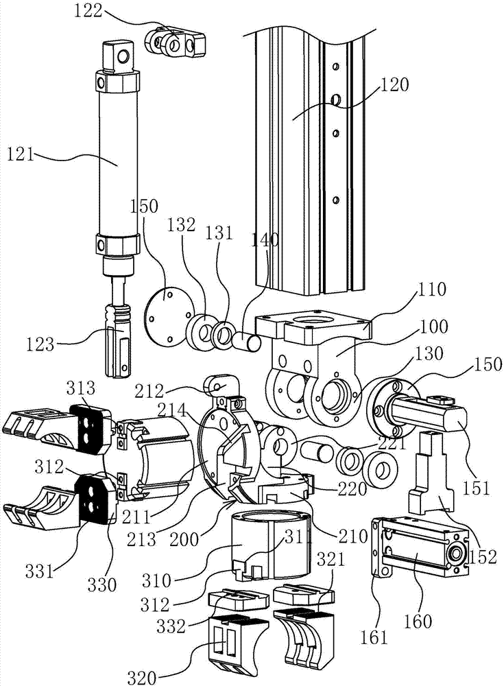
[0037] Such as figure 1 , figure 2 As shown, a swing type rotary air gripper 300 device of the present invention includes a fixed seat 100 , a rotating seat 200 and an air gripper 300 .

[0038] The fixed seat 100 is a square body block structure erected. The upper edge of the fixed seat 100 protrudes outwards and forms a fixed part 110 at the upper end of the fixed seat 100. The upper surface of the fixed part 110 is connected with the vertically arranged manipulator arm 120 Fixed connection, the rotating seat 200 is movably connected with the fixed seat 100 and can rotate relative to the fixed seat 100. There are two air grippers 300 and they are respectively connected with the rotating seat 200. The two air grippers 300 are perpendicular to each other and located in the same plane

[0039] In the initial state, one of the air grippers 300 is set horizontally, and the other air gripper 300 is set upright. The two air grippers 300 are located in the same horizontal plane. A...

Embodiment 2

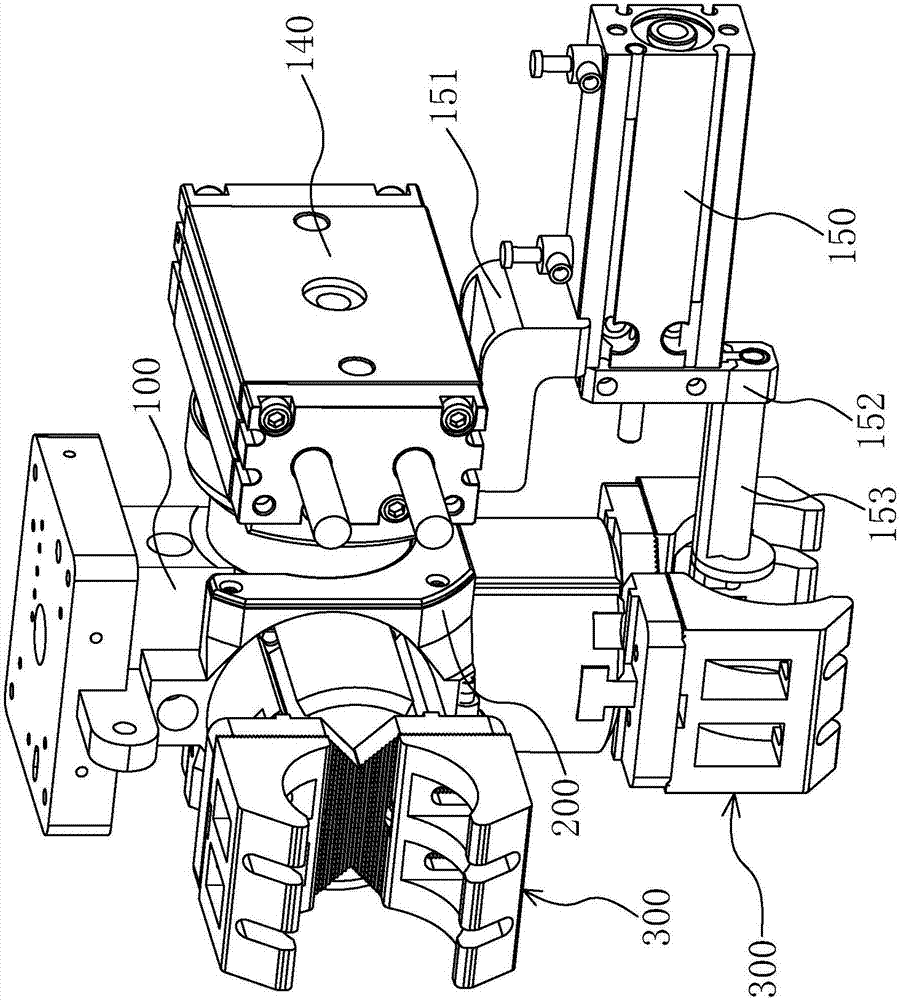
[0063] The inventive concept and working principle of this embodiment are basically the same as those of the embodiment, except that the structure of the rotating base 200, the connection structure between the rotating base 200 and the fixed base 100, and the driving method of the rotating base 200 are described in detail as follows:

[0064] Such as image 3 , Figure 4 As shown, a swing type rotary air gripper 300 device of the present invention also includes a fixed seat 100 , a rotating seat 200 and an air gripper 300 .

[0065] The structures of the fixed seat 100 and the air gripper 300 are the same as those in Embodiment 1, while the rotating seat 200 is similar to a plate-shaped structure, and its middle is bent in a right-angled arc shape, so that the two ends of the rotating seat 200 are perpendicular to each other, and one end is erected , the other end is arranged horizontally, and an installation groove 210 for installing the air gripper 300 is also provided on t...


PUM


Abstract

The invention provides a swinging type rotation gas claw device, and belongs to the technical field of mechanical arms. The technical problems that an existing mechanical arm is large in size, and space needed for rotation is large are solved. According to the technical scheme, the swinging type rotation gas claw device comprises a fixed base used for being connected with a mechanical arm body, rotation bases movably connected with the fixed base, and two gas claws connected with the rotation bases. The rotation bases can rotate relative to the fixed base, and the two gas claws can swing back and forth along with the rotation bases. The swinging type rotation gas claw device has the beneficial effects that the two gas claws can swing back and forth in the same plane along with the rotation base, in other words, and the two rotation bases rotate in the same plane but not rotate in the three-dimensional space; and compared with a traditional rotation gas claw structure, the occupied space of the swinging type rotation gas claw device is small, space needed for rotation is small, using of the whole rotation gas claw structure is more flexible, and the using range is wider.

Description

technical field [0001] The invention belongs to the technical field of manipulators, and relates to a rotary air claw device, in particular to a swing type rotary air claw device. Background technique [0002] With the development of the machinery manufacturing industry, there are more and more CNC lathes. In order to meet the requirements of multi-variety and small batch production and increase productivity, the CNC lathes are equipped with shaft parts loading and unloading systems, which are required to be able to transport bars and unload them of different sizes. For shafts and sheet parts, people use mechanical cutting automation equipment to process metal workpieces, which improves the processing efficiency and has high safety performance. [0003] At present, the most widely used loading and unloading device in mechanical cutting processing automation equipment is the rotary air claw device. The rotary cylinder is fixed on the inclined side of the rotary frame. The fi...

Claims


Application Information

Patent Timeline
Patent Type & Authority Applications(China)
IPC IPC(8): B23Q7/04B23B15/00
CPCB23Q7/048
Inventor 杨云林
Owner 宁波开浦智能科技有限公司
Why Eureka
Try Eureka