
Waist motion bionic structure and bionic machine rat including waist motion bionic structure

A waist and driver technology, which is applied in the field of bionic robot mice, can solve the problems of not being able to accurately reflect the movement of the reptile's waist, not being able to accurately reflect the freedom of movement of the reptile's waist, and not being able to reflect compactness.

Pending Publication Date: 2017-11-28
INST OF AUTOMATION CHINESE ACAD OF SCI
View PDF8 Cites 3 Cited by
  • Summary
  • Abstract
  • Description
  • Claims
  • Application Information

AI Technical Summary

Problems solved by technology

[0003] Although the existing bionic robot mice can meet the most basic ornamental requirements, there are still the following defects in the research of biologists, neuroscientists and brain researchers on the movement principles, behavioral characteristics and interaction methods of mice. 1) Due to the long size of the bionic robot, the waist structure of the bionic robot cannot reflect the compactness of the waist structure of the shorter bionic robot mouse; 2) The waist driving device of the bionic robot cannot accurately reflect the waist movement of reptiles , that is, it cannot accurately reflect the freedom of movement of the reptile waist; 3) The difference between the shape structure of the bionic robot waist and the bionic robot mouse waist structure affects researchers' research on the interaction mode of the bionic robot mouse

Method used


Image

  • Waist motion bionic structure and bionic machine rat including waist motion bionic structure
  • Waist motion bionic structure and bionic machine rat including waist motion bionic structure
  • Waist motion bionic structure and bionic machine rat including waist motion bionic structure

Examples


Embodiment Construction

[0022] First of all, those skilled in the art should understand that these implementations are only used to explain the technical principles of the present invention, and are not intended to limit the protection scope of the present invention. Those skilled in the art can make adjustments as needed to adapt to specific application occasions. For example, although the first driver is pivotally connected to the frame and the second driver is pivotally connected to the first driver in this specification, the driving device in this specification is not limited to this connection method, and the driving device in this specification can also be The second driver is pivotally connected to the frame, and the first driver is pivotally connected to the second driver. This variation does not depart from the principle and scope of the present invention.

[0023] It should be noted that, in the description of the present invention, the terms "up", "down", "left", "right", "vertical", "hori...


PUM


Abstract

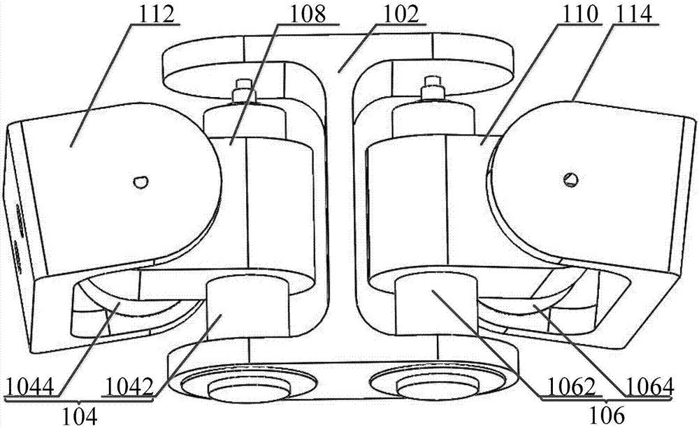
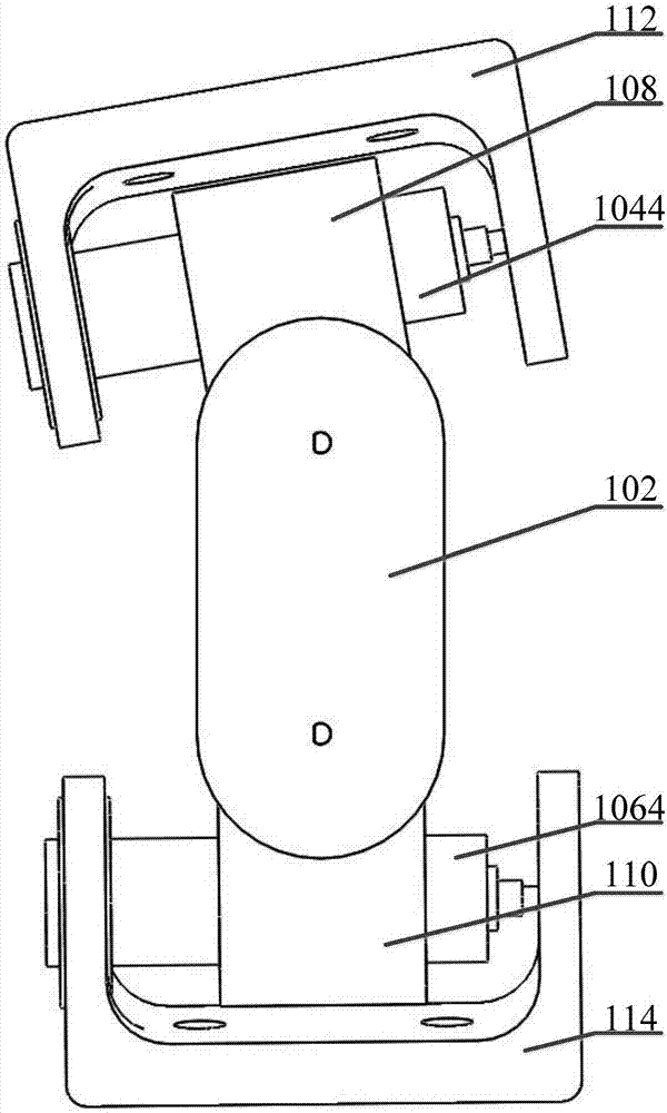
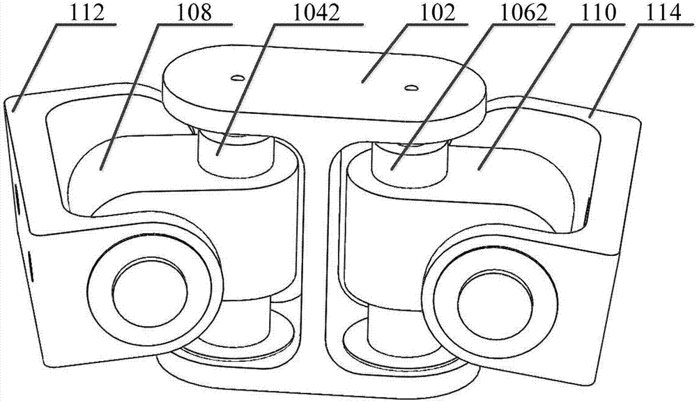
The invention relates to the technical field of bionic structures, in particular to a waist motion bionic structure and a bionic machine rat including the waist motion bionic structure. The waist motion bionic structure aims at solving the problem that in the prior art, motion flexibility and structural compactness of a waist motion bionic structure in the prior art are poor. In order to achieve the aim, the waist motion bionic structure comprises a rack, a front drive device and a rear drive device, wherein the front drive device is connected to the front end of the rack in a pivot manner, and is used for driving a front limb at the front end of the rack to swing left and right and up and down; the rear drive device is connected to the rear end of the rack in a pivot manner and is used for driving a rear limb at the rear end of the rack to swing left and right and up and down. Through the technical scheme, motion flexibility and structure compactness of the waist motion bionic structure are improved, consistency of the waist motion bionic structure and an animal waist structure is improved, research of biologists, neuroscientists and brain researchers for the waist structure is facilitated, and the effective control over the behavior of the waist structure is achieved.

Description

technical field [0001] The invention relates to the technical field of bionic structures, in particular to a waist motion bionic structure and a bionic robot mouse including the waist motion bionic structure. Background technique [0002] With the development of bionic structure technology, the technology of bionic structure in terms of motion and structure is becoming more and more mature, especially the technology of bionic robot is the most mature. The closest to perfection, in view of the bionic robots that are approaching perfection, scientists and technicians often copy the motion principles and structural shapes of bionic robots to other bionic animals, for example, the bionic robot mouse uses a driving mechanism and shape similar to bionic robots structure. [0003] Although the existing bionic robot mice can meet the most basic ornamental requirements, there are still the following defects in the research of biologists, neuroscientists and brain researchers on the ...

Claims


Application Information

Patent Timeline
Patent Type & Authority Applications(China)
IPC IPC(8): B25J17/00
CPCB25J17/00
Inventor 王子荣乔红
Owner INST OF AUTOMATION CHINESE ACAD OF SCI
Learn More