Workpiece automatic overturning device

An automatic turning and workpiece technology, applied in the field of parts processing, can solve the problems of serious parts bumping, low work efficiency, and lower appearance quality, and achieve the effects of reducing bumps, saving space, and reducing costs.

Inactive Publication Date: 2017-11-28
天津华伟精工电子有限公司
View PDF0 Cites 3 Cited by
  • Summary
  • Abstract
  • Description
  • Claims
  • Application Information

AI Technical Summary

Problems solved by technology

[0004] 1. High labor costs and increased costs;
[0005] 2. The frequency of handling is high, which leads to serious collision of parts and reduces the appearance quality;
[0006] 3. Low work efficiency

Method used


Image

  • Workpiece automatic overturning device
  • Workpiece automatic overturning device
  • Workpiece automatic overturning device

Examples


Embodiment Construction

[0023] The present invention will be further described in detail below in conjunction with the accompanying drawings and through specific embodiments.

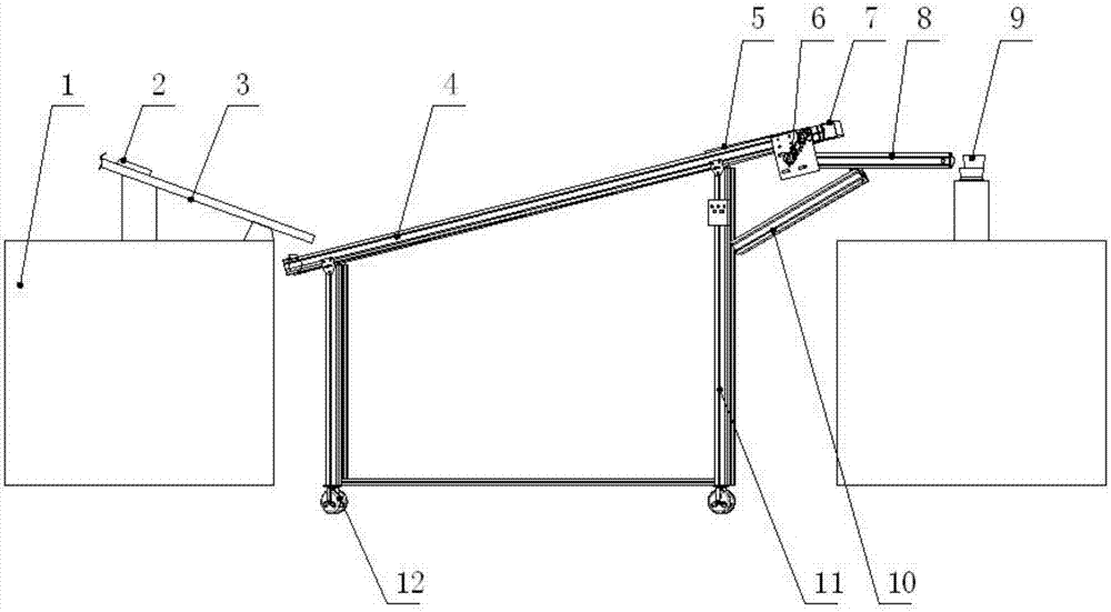
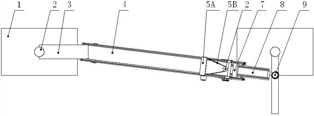
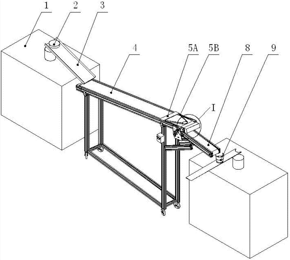
[0024] A workpiece automatic turning device, such as Figures 1 to 3 As shown, it includes a cabinet body 1, a material plate 3, a first conveyor belt 4, and a second conveyor belt 8. A material plate inclined downward is installed on the cabinet body, and a first inclined upward plate is installed at the discharge port of the material plate. Conveyor belt, the feed end of this first conveyor belt is corresponding to the discharge end of material board, and the discharge end of this first conveyor belt is equipped with turning mechanism 7, and this turning mechanism comprises turning box 7B and turning over bar 7A, as Figure 4 As shown, the flipping gear bar is vertically worn in the flip box, and the second conveyor belt is installed horizontally below the flip mechanism, and the automatic feeder 9 is installed below the dis...


PUM


Abstract

The invention relates to an automatic workpiece turning device, which includes a cabinet body, a material board, a first conveyor belt and a second conveyor belt. A conveyor belt, the feed end of the first conveyor belt corresponds to the discharge end of the material plate, the discharge end of the first conveyor belt is equipped with a turning mechanism, and the workpiece is turned over by the turning mechanism and sent to the second conveyor belt, and the second conveyor belt goes out An automatic feeder is installed under the material end. The device realizes accurate workpiece positioning and turning action through a positioning mechanism and a turning mechanism, and has a simple structure and a reasonable design. The invention has the advantages of simple structure, scientific and reasonable design, and ingenious conception, which reduces the transport frequency between workpiece processes, saves space, reduces the collision of workpieces, ensures the stability of products and equipment, saves physical strength of employees, reduces costs, and improves production efficiency.

Description

technical field [0001] The invention belongs to the field of parts processing, in particular to an automatic turning device for workpieces. Background technique [0002] In the process of processing the T iron, U iron and other parts of the loudspeaker, the manufacturer has a deburring process: the specific process is to first remove the burr on the upper end surface through the equipment, and then manually transfer the workpiece to another process. Turn the workpiece over 180 degrees, put it into the next process and continue to remove the burr on the other end of the workpiece. [0003] The problems with the above operations are: [0004] 1. High labor costs and increased costs; [0005] 2. The frequency of handling is high, which leads to serious collision of parts and reduces the appearance quality; [0006] 3. Low work efficiency. Contents of the invention [0007] The object of the present invention is to overcome the deficiencies of the prior art and provide an ...

Claims


Application Information

Patent Timeline
Patent Type & Authority Applications(China)
IPC IPC(8): B65G47/248
CPCB65G47/248
Inventor 乔俊亮赵洲
Owner 天津华伟精工电子有限公司
Why Eureka
Try Eureka