Gas intake system of atomic layer deposition device and method of gas intake system

A technology of atomic layer deposition and air intake system, which is applied in the direction of coating, gaseous chemical plating, metal material coating process, etc., can solve the problems of low utilization rate and low production efficiency of atomic layer deposition equipment, and achieve the improvement of utilization rate , Improve efficiency and reduce idle time

Inactive Publication Date: 2017-11-28
北京芯微诺达科技有限公司
View PDF5 Cites 5 Cited by
  • Summary
  • Abstract
  • Description
  • Claims
  • Application Information

AI Technical Summary

Problems solved by technology

This leads to low utilization of precursor supply equipment and low production efficiency of ALD equipment

Method used


Image

  • Gas intake system of atomic layer deposition device and method of gas intake system
  • Gas intake system of atomic layer deposition device and method of gas intake system

Examples


Embodiment 1

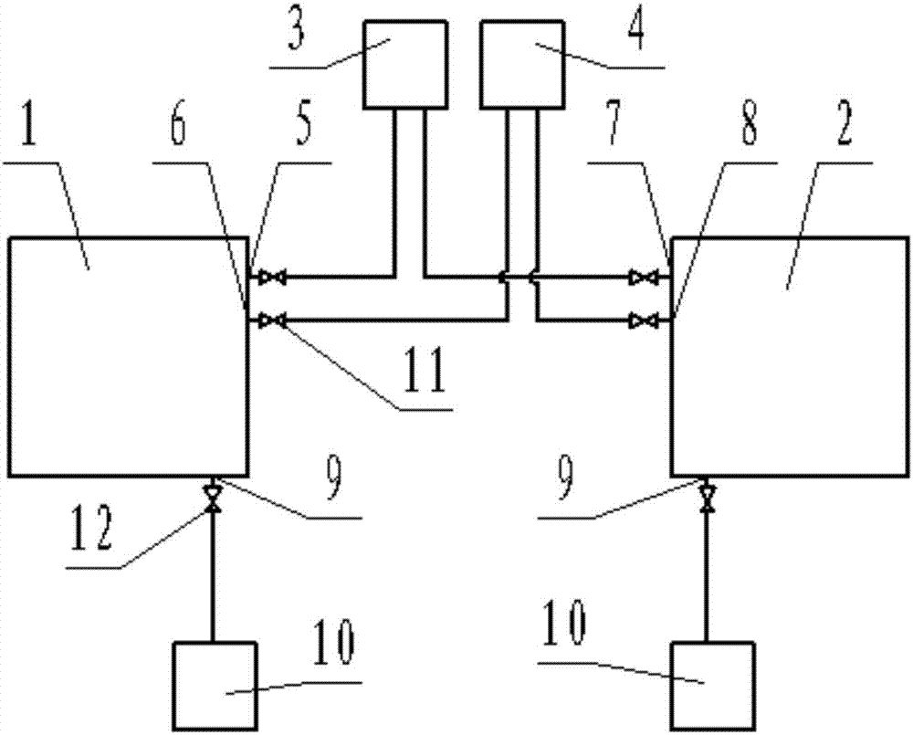
[0030] Embodiment 1: as figure 1 As shown, this embodiment provides an air intake system of an atomic layer deposition apparatus, which includes a first reaction chamber 1 and a second reaction chamber 2 that are independent from each other. The first reaction chamber 1 is provided with a first air inlet 5 and a second air inlet 6, and the second reaction chamber 2 is provided with a third air inlet 7 and a fourth air inlet 8, and the first air inlet 5 A first gas source 3 is connected to the third air inlet 7 through a pipeline, and the first gas source 3 is used to supply gaseous organic sources (such as trimethylaluminum) to the first reaction chamber 1 and the second reaction chamber 2 . The second air inlet 6 and the fourth air inlet 8 are connected with a second gas source 4 by pipeline, and the second gas source 4 is used to supply gaseous water in the first reaction chamber 1 and the second reaction chamber 2, ( It can also match other gaseous organic sources as oxyg...

Embodiment 2

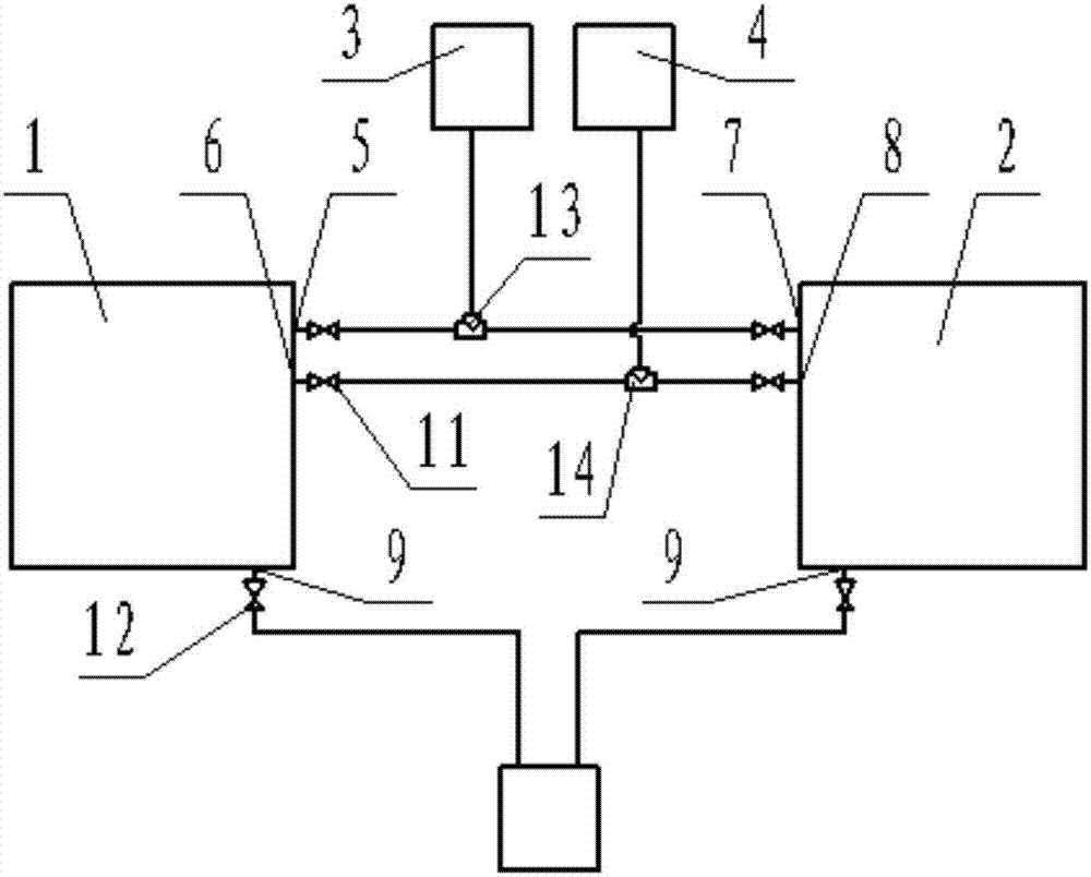
[0038] Embodiment 2: as figure 2 As shown, the difference between this embodiment and Embodiment 1 is that: the two exhaust ports 9 are connected to a vacuum pump 10 through pipelines, and the pipelines between the two exhaust ports 9 and the vacuum pump 10 are respectively provided with an exhaust switch valve. 12. The first air inlet 5, the third air inlet 7 and the first air source 3 are connected with a first three-way valve 13 through a pipeline, and the first air inlet 5 and the third air inlet 7 are connected to the first three-way valve 13. An intake switch valve 11 is respectively arranged between them. The second air inlet 6, the fourth air inlet 8 and the second air source 4 are connected with a second three-way valve 14 through pipelines, and the second air inlet 6 and the fourth air inlet 8 are connected with the second three-way valve 14 An intake switch valve 11 is respectively arranged between them.

[0039]In this embodiment, a three-way valve is used to c...


PUM


Abstract

The invention discloses a gas intake system of an atomic layer deposition device. The gas intake system comprises mutually independent first reaction chamber and second reaction chamber, wherein the first reaction chamber is provided with a first gas intake opening and a second gas intake opening; the second reaction chamber is provided with a third gas intake opening and a fourth gas intake opening; the first gas intake opening and the third gas intake opening are connected with a first gas source through pipelines; the second gas intake opening and the fourth gas intake opening are connected with a second gas source through pipelines; the first reaction chamber and the second reaction chamber are provided with a gas exhaust opening respectively; two gas exhaust openings are connected with a vacuum pump through pipelines. The gas intake system can be used for improving the utilization ratios of the first gas source and the second gas source, and is used for reducing the idle times of the gas sources and improving the overall film forming efficiency.

Description

technical field [0001] The invention relates to the technical field of atomic layer deposition, in particular to an air intake system of atomic layer deposition equipment and a method thereof. Background technique [0002] Atomic layer deposition (ALD for short) is a method that can coat substances layer by layer on the surface of a substrate in the form of a single atomic film. [0003] Atomic layer deposition is a method of forming a deposited film by alternating pulses of gaseous precursors into the reactor and chemically adsorbing and reacting on the deposition substrate. The first precursor is imported to the surface of the matrix material and held on the surface by chemisorption (saturated adsorption). When the second precursor is passed into the reactor, it will react with the first precursor that has been adsorbed on the surface of the substrate material. A displacement reaction will occur between the two precursors and produce corresponding by-products until the f...

Claims


Application Information

Patent Timeline
IPC IPC(8): C23C16/455
CPCC23C16/45548
Inventor 卢艳
Owner 北京芯微诺达科技有限公司
Why Eureka
Try Eureka