
Electronic distribution frame based on EMI

An electronic distribution frame and distribution frame technology, applied in electrical components, read/write/query/recognition near-field transmission systems, transmission systems, etc., can solve the relationship between the switch port and the distribution frame port that cannot be detected, Reduced cabling management efficiency, failure to detect jumper insertion and changes at the switch side, etc.

Inactive Publication Date: 2017-11-28
SUZHOU HUIHUA ELECTRONICS TECH
View PDF5 Cites 1 Cited by
  • Summary
  • Abstract
  • Description
  • Claims
  • Application Information

AI Technical Summary

Problems solved by technology

[0004] However, for port detection, it is necessary to set switches in the ports of the distribution frame and the switch, so as to identify whether there is a jumper on the port, but the position of the jumper and the relationship between the switch port and the port of the distribution frame cannot be detected; It needs to be applied to the dual distribution frame system, and it cannot detect the jumper plugging and changing operations at the switch end, so the relationship between the switch port and the distribution frame port cannot be detected.
Therefore, the existing electronic wiring management still cannot effectively realize refined management, and its wiring management efficiency is reduced, thereby increasing the probability of network physical layer failures, which in turn causes the problem of poor network stability.

Method used


Image

  • Electronic distribution frame based on EMI

Examples


specific Embodiment

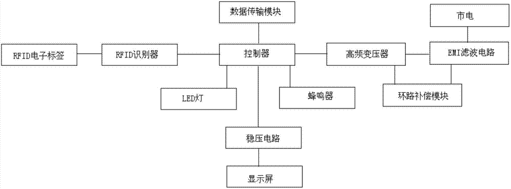
[0057] The specific implementation example is as follows: RFID electronic distribution frame system is mainly composed of four functional modules: RFID electronic jumper, RFID electronic distribution frame, controller and background computer management software. The core is RFID electronic jumper and RFID electronic distribution frame . RFID electronic jumper is to add an RFID electronic tag with a unique identity on the ordinary jumper, which contains data such as the type and speed of the jumper, so the RFID electronic jumper can also be called a smart jumper; RFID electronic wiring The RFID identifier is embedded in the ordinary distribution frame, which not only has the function of the ordinary distribution frame, but also can identify the RFID electronic jumper; the function of the controller is to connect with multiple RFID electronic distribution frames to control multiple The RFID electronic distribution frame can display the cable connection status of the current netw...


PUM


Abstract

The invention discloses an electronic distribution frame based on EMI. The electronic distribution frame comprises a distribution cabinet, a plurality of jumper wires and a plurality of distribution frames which are arranged in the distribution cabinet. Each jumper wire is provided with an RFID electronic label for unique identity identification. An RFID identifier is embedded into the distribution frame. The distribution cabinet is internally provided with a controller, a data transmission module, an LED lamp, a buzzer and a display screen, wherein the data transmission module, the LED lamp, the buzzer and the display screen are connected with the controller. The distribution cabinet is internally provided with an EMI filtering circuit, a high-frequency transformer and a loop compensation module. According to the electronic distribution frame, each common distribution frame is provided with the RFID identifier. When an RFID electronic jumper wire is inserted into a certain port of a network distribution frame, the electronic distribution frame can accurately monitor the condition of each port link of the network distribution frame. The electronic distribution frame is further provided with components such as an LED lamp and a buzzer for assisting operation of the jumper wire. Furthermore a work ticket of the jumper wire is displayed on the controller end and simultaneous voice playing in the jumper wire operation is performed.

Description

technical field [0001] The invention belongs to the field of intelligent control of distribution frames, in particular to an electronic distribution frame based on EMI RFID. Background technique [0002] In the integrated wiring of the network, the distribution frame provides an interface for the connection between the network cable and the network device (such as: a switch), and when the line in the integrated wiring changes (such as: port movement, addition or change, etc.) , can be realized through the jumper between the distribution frame and the network equipment. In addition, in the current network cabling system, cabling management, that is, port changes between distribution frames and switches, needs to be searched, updated and recorded manually. However, in a network environment with many information points, the wiring management work is cumbersome, error-prone, and changes are not recorded in time. [0003] In order to solve the above problems, at present, in the...

Claims


Application Information

Patent Timeline
IPC IPC(8): H04Q1/14H04Q1/22H04Q1/02H04B5/00
CPCH04Q1/116H04Q1/14H04Q1/22H04B5/77
Inventor 黄敏
Owner SUZHOU HUIHUA ELECTRONICS TECH
Learn More