
RFID electronic wire distribution frame based on AD/DC conversion circuit

An electronic distribution frame and conversion circuit technology, applied in the direction of electrical components, advanced technology, sustainable communication technology, etc., can solve the problem that the relationship between the jumper position switch port and the distribution frame port cannot be detected, and the switch port cannot be detected The relationship with the patch panel port, the inability to detect the plugging and changing of the jumper on the switch side, etc., achieve the effect of low standby power consumption, fast speed, and easy implementation

Inactive Publication Date: 2018-01-23
SUZHOU HUIHUA ELECTRONICS TECH
View PDF5 Cites 0 Cited by
  • Summary
  • Abstract
  • Description
  • Claims
  • Application Information

AI Technical Summary

Problems solved by technology

[0004] However, for port detection, it is necessary to set switches in the ports of the distribution frame and the switch, so as to identify whether there is a jumper on the port, but the position of the jumper and the relationship between the switch port and the port of the distribution frame cannot be detected; It needs to be applied to the dual distribution frame system, and it cannot detect the jumper plugging and changing operations at the switch end, so the relationship between the switch port and the distribution frame port cannot be detected.
Therefore, the existing electronic wiring management still cannot effectively realize refined management, and its wiring management efficiency is reduced, thereby increasing the probability of network physical layer failures, which in turn causes the problem of poor network stability.

Method used


Image

  • RFID electronic wire distribution frame based on AD/DC conversion circuit

Examples


specific Embodiment

[0051] The specific implementation example is as follows: RFID electronic distribution frame system is mainly composed of four functional modules: RFID electronic jumper, RFID electronic distribution frame, controller and background computer management software. The core is RFID electronic jumper and RFID electronic distribution frame . RFID electronic jumper is to add an RFID electronic tag with a unique identity on the ordinary jumper, which contains data such as the type and speed of the jumper, so the RFID electronic jumper can also be called a smart jumper; RFID electronic wiring The RFID identifier is embedded in the ordinary distribution frame, which not only has the function of the ordinary distribution frame, but also can identify the RFID electronic jumper; the function of the controller is to connect with multiple RFID electronic distribution frames to control multiple The RFID electronic distribution frame can display the cable connection status of the current netw...


PUM


Abstract

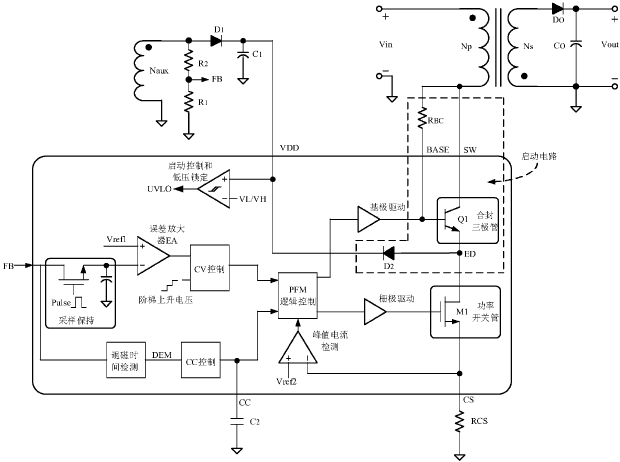
The invention discloses an RFID electronic wire distribution frame based on an AD / DC conversion circuit. The RFID electronic wire distribution frame comprises a wire distribution cabinet, and a plurality of jumper wires and a plurality of electronic wire distribution frames set in the wire distribution cabinet, wherein RFID electronic tags for unique identity identification are added to the jumperwires; RFID identifiers are embedded into the wire distribution frames; a controller, and a data transmission module, an LED lamp, a beeper and a display screen connected with the controller are setin the wire distribution cabinet; the AD / DC conversion circuit, a charge control module and a storage battery module which are connected in sequence are also set in the wire distribution cabinet; andthe AD / DC conversion circuit is used for converting a commercial alternating current into a direct current, and the storage battery module is charged through the charge control module. According to the RFID electronic wire distribution frame, through setting of the AD / DC conversion device, an external starting circuit is removed, so the power consumption of a starting part is greatly reduced. According to the RFID electronic wire distribution frame, the starting is realized through adoption of a sealed triode, the standby power consumption is low and the speed is fast. According to the RFID electronic wire distribution frame, through adoption of a seal technology, a high voltage technology is avoided, the realization is easy, and the cost is reduced. When output short circuit occurs, a system automatically enters a fixed frequency mode, so the stability is improved.

Description

technical field [0001] The invention belongs to the field of intelligent control of distribution frames, in particular to an RFID electronic distribution frame based on an AD / DC conversion circuit. Background technique [0002] In the integrated wiring of the network, the distribution frame provides an interface for the connection between the network cable and the network device (such as: a switch), and when the line in the integrated wiring changes (such as: port movement, addition or change, etc.) , can be realized through the jumper between the distribution frame and the network equipment. In addition, in the current network cabling system, cabling management, that is, port changes between distribution frames and switches, needs to be searched, updated and recorded manually. However, in a network environment with many information points, the wiring management work is cumbersome, error-prone, and changes are not recorded in time. [0003] In order to solve the above prob...

Claims


Application Information

Patent Timeline
IPC IPC(8): H04Q1/14H04B5/00H04Q1/22
CPCY02D30/70
Inventor 黄敏
Owner SUZHOU HUIHUA ELECTRONICS TECH
Learn More