Rotation washing mirror of built-in storage device

A storage device and rotary technology, applied in the field of bathroom mirrors, can solve the problems of inconvenience, low practicability, and single function of bathroom mirrors, and achieve the effects of convenient dressing, increased practicability, and increased space utilization.

Inactive Publication Date: 2017-12-01
刘代学
View PDF0 Cites 1 Cited by
  • Summary
  • Abstract
  • Description
  • Claims
  • Application Information

AI Technical Summary

Problems solved by technology

[0004] The technical problem to be solved by the present invention is that under the limited use space of the bathroom, the function of the bathroom mirror is single and the practicability is low. The bathroom mirror has a single function and low practicability, which brings a lot of inconvenience to the user

Method used


Image

  • Rotation washing mirror of built-in storage device

Examples


Embodiment 1

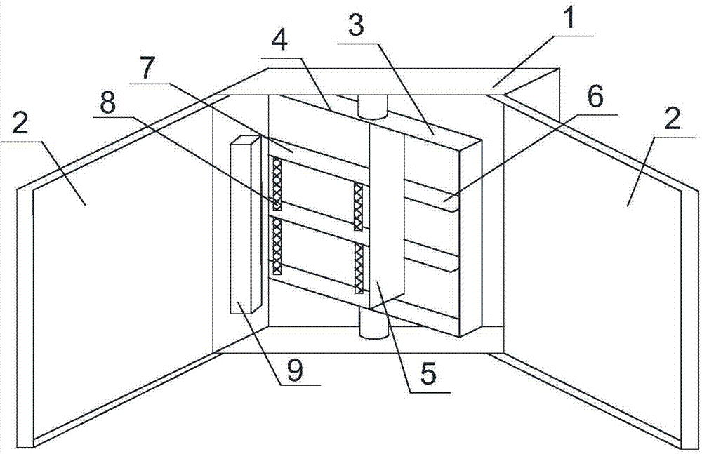
[0022] Such as figure 1 As shown, the rotating toilet mirror with a built-in storage device of the present invention includes a mirror frame 1. A double-open mirror body 2 is installed on the front of the mirror frame 1 away from the wall surface. A rotating mirror body 3 is installed inside the mirror frame 1. The upper and lower ends of the mirror body 3 are rotatably connected with the frame wall of the mirror frame 1 on the same side. One side of the rotating mirror body 3 is a mirror surface, and the other side of the rotating mirror body 3 opposite to the mirror surface is equipped with a storage cabinet 4, the storage cabinet 4 A partition 5 is installed inside. The storage cabinet 4 on one side of the partition 5 is horizontally fixed with at least two first storage boards 6 arranged in parallel. The storage cabinet 4 on the other side of the partition 5 is slidably installed inside at least two The evenly arranged second shelf 7, the wall of the partition 5 and the inn...

Embodiment 2

[0025] Based on the embodiment 1, two springs 8 are installed between adjacent second storage boards 7, and the two springs 8 are respectively located at two ends of the second storage board 7, adjacent to the second storage board on the inner bottom wall of the storage cabinet 4. 7 and the inner bottom wall of the storage cabinet 4 are also connected by a spring 8. The sliding of the second shelf is to adjust the space between the shelf or between the shelf and the inner wall of the shelf; on the one hand, the spring can strengthen the stability of the second shelf, and on the other hand, it reduces the placing of larger items on the shelf. After placing the items, the distance between adjacent storage boards is automatically adjusted to the minimum, which further increases the space utilization rate inside the storage cabinet.

Embodiment 3

[0027] Based on the above embodiment, a fan 9 is installed on one inner wall of the mirror frame 1, and a plurality of evenly distributed vents are provided on the other side wall of the mirror frame 1 opposite to the fan 9. The fan is used to keep the inside of the mirror frame in a dry environment to prevent the items placed in the locker from getting damp or breeding bacteria. The fan is preferably a micro-micro fan, which consumes less power, has a small air volume, is convenient for long-term use, and saves electricity and energy.


PUM


Abstract

The invention discloses a rotary washing mirror with a built-in storage device. The frame wall is rotationally connected, one side of the rotating mirror body is a mirror surface, and the other side of the rotating mirror body opposite to the mirror surface is installed with a locker, and a partition is installed inside the locker, and at least two parallel cabinets are horizontally fixed inside the locker on one side of the partition. Arranged first storage boards, the inside of the locker on the other side of the partition is slidingly installed with at least two second storage boards arranged evenly. slide rails. The invention changes the structure of the traditional bathroom mirror, increases the space utilization rate of the bathroom mirror, further increases the space utilization rate of the bathroom, makes the bathroom mirror have functions other than imaging, and has high practicability.

Description

Technical field [0001] The invention relates to a bathroom mirror, in particular to a rotating washing mirror with a built-in storage device. Background technique [0002] The bathroom mirror, as the name implies, is a mirror placed in the bathroom for washing up. The bath mirror is an indispensable part of the bathroom space. The clear and bright bath mirror brings a good mood when dressing up. Don't look at the appearance of bath mirrors and ordinary mirrors. In fact, there are a lot of exquisiteness inside. [0003] At present, most bathroom mirrors directly fix a traditional mirror body on the wall above the sink, which can only play a simple imaging role. In fact, the current use of more bathroom mirrors is not convenient for people to dress up. In this space, the cosmetics, common toiletries, and spare toiletries used by people are placed separately or stored directly, and they are taken out each time they are used, which is inconvenient to use. Moreover, the bathroom space...

Claims


Application Information

Patent Timeline
Patent Type & Authority Applications(China)
IPC IPC(8): A47G1/02A47B57/00A47B57/06A47B67/00
CPCA47G1/02A47B57/00A47B57/06A47B67/005
Inventor 刘代学
Owner 刘代学
Why Eureka
Try Eureka