Plastic mould

A technology of plastic molds and inserts, applied in the field of mold equipment, can solve the problems of decreased production efficiency of molds, inability to connect, and complicated operation by staff, and achieves the effect of stable cooperation and improved production efficiency.

Active Publication Date: 2017-12-01
ZHEJIANG SAIHAO IND CO LTD
View PDF8 Cites 5 Cited by
  • Summary
  • Abstract
  • Description
  • Claims
  • Application Information

AI Technical Summary

Problems solved by technology

[0005] Although the above-mentioned cutting and bending die and continuous stamping die have achieved demoulding of plastic parts to a certain extent, the cutting and bending die and continuous stamping die are only provided with air guide channels on the core, and do not There is no cooling channel or cooling cavity for cooling the plastic part, which leads to the situation that the plastic part is easily bonded to the core during the demoulding process, and the demoulding of the plastic part is incomplete. Cooling pipes or gas cooling passages are used to cool plastic parts, but the setting of this structure requires multiple air inlet pipes or liquid inlet pipes outside the mold, which leads to a large improvement in the mold, and the staff needs to Controlling multiple inlet pipes or liquid inlet pipes makes the operation of the staff complicated, and it is easy to make mistakes during the injection molding process. At the same time, the two processes of cooling and demoulding cannot be completely connected, which reduces the production efficiency of the entire mold.

Method used


Image

  • Plastic mould
  • Plastic mould
  • Plastic mould

Examples


Embodiment Construction

[0038] The following are specific embodiments of the present invention and in conjunction with the accompanying drawings, the technical solutions of the present invention are further described, but the present invention is not limited to these embodiments.

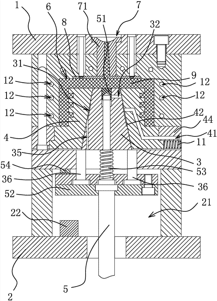
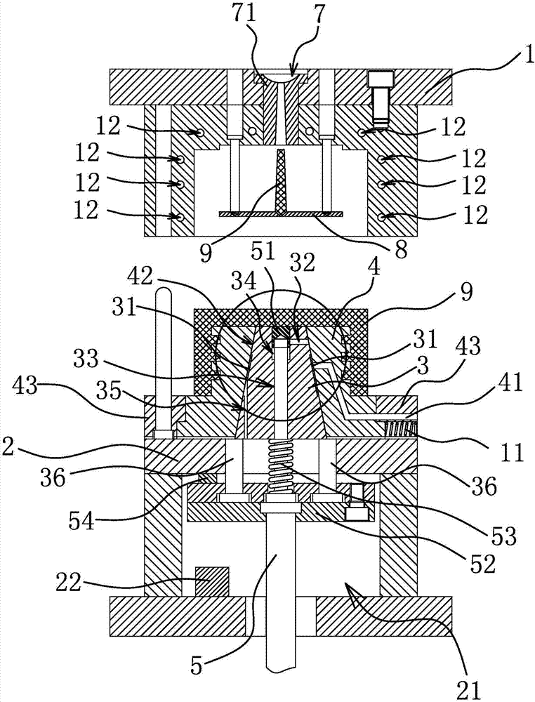
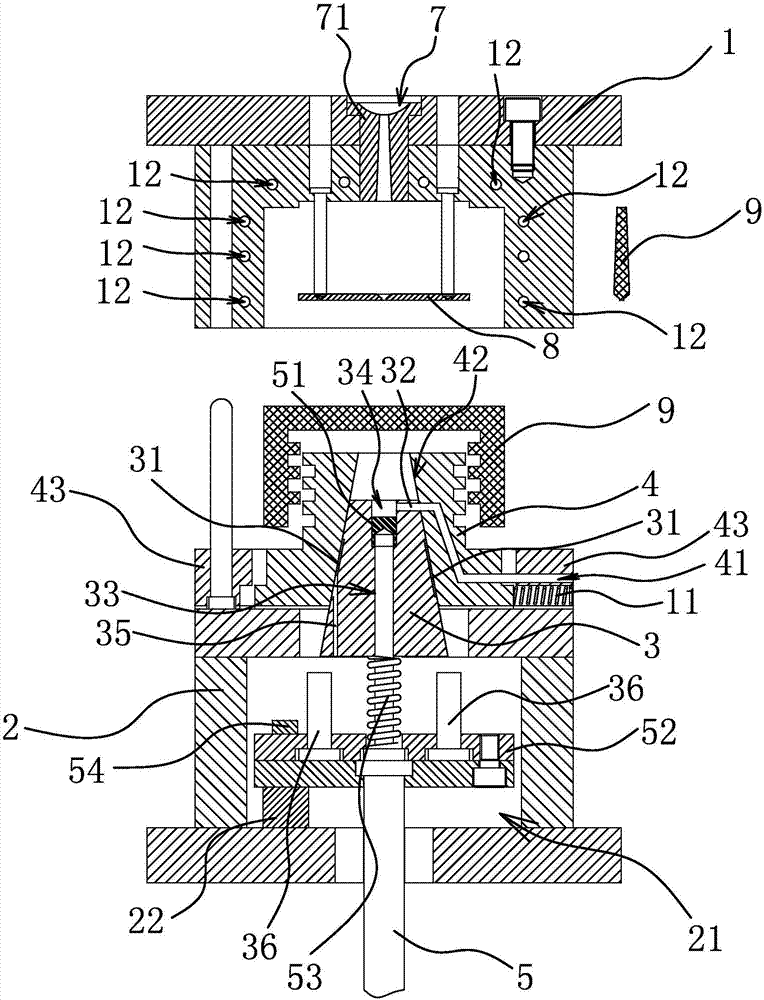
[0039] Such as figure 1 As shown, the plastic mold includes an upper module 1 and a lower module 2, an insert 3 and a core 4 are arranged between the upper module 1 and the lower module 2, and the insert 3 is provided with a gas cooling channel 31 along the circumferential direction.

[0040] Specifically, if Figure 1-4 As shown, the upper module 1 is provided with a flow channel 7 for molten plastic to flow in, the upper module 1 is also provided with a flow channel bushing 71, and the insert 3 is provided with a slide bar 5, which can move along the insert 3 slides axially and drives the insert 3 to move axially along the core 4. The insert 3 is also provided with an air guide channel 32 passing through the insert 3 in...


PUM


Abstract

The invention provides a plastic mould, and belongs to the technical field of mould equipment. The plastic mould solves the problem that the production efficiency of an existing plastic mould is low. The plastic mould comprises an upper mould block and a lower mould block, a moulding cavity is formed between the upper mould block and the lower mould block, an insert and a mould core are arranged between the upper mould block and the lower mould block, air cooling channels are formed in the circumferential direction of the insert, a through hole axially penetrating through the insert is formed in the insert, the through hole communicates with the moulding cavity, a limiting groove is formed in the hole wall of the through hole, the insert is slidably connected with a slide rod in the through hole, the end portion of the slide rod is embedded into the limiting groove and abuts against the groove wall of the limiting groove, an air guide channel is formed in the insert, and an air inlet pipe is arranged on the mould core. The plastic mould can improve the production efficiency of the mould.

Description

technical field [0001] The invention belongs to the technical field of mold equipment and relates to a plastic mold. Background technique [0002] At present, in the process of most injection molding, liquid or gas is used to cool the plastic parts. Only one of the methods is used to cool the plastic parts, which will cause the cooling of the plastic parts to be incomplete, and most plastic parts are molded. Finally, the upper module is ejected through the inclined rod to realize demoulding, which often leads to incomplete demoulding. [0003] In response to the above problems, people have developed a variety of plastic molds: [0004] For example, a Chinese patent application (patent application number: 201420096441.1) discloses a cutting and bending die and a continuous stamping die, including an upper die, a lower die and a demoulding device. The demoulding device is arranged on the lower die and can blow gas to the processing Good workpiece, make the workpiece out of t...

Claims


Application Information

Patent Timeline
Patent Type & Authority Applications(China)
IPC IPC(8): B29C45/26B29C45/33B29C45/43B29C45/73
CPCB29C45/26B29C45/2602B29C45/33B29C45/43B29C45/73
Inventor 李金国
Owner ZHEJIANG SAIHAO IND CO LTD
Why Eureka
Try Eureka