Bearing blank automatic turnover mechanism

A technology of automatic inversion and shaft blank, applied to conveyor objects, transportation and packaging, etc., can solve problems such as conveyor bumps, shaft blank deformation, conveyor impact, etc., to achieve no impact and bumps, improve continuity and The degree of automation, the effect of smooth and reliable flipping

Inactive Publication Date: 2017-12-01
大连美嘉洛机器人科技有限公司
View PDF6 Cites 0 Cited by
  • Summary
  • Abstract
  • Description
  • Claims
  • Application Information

AI Technical Summary

Problems solved by technology

At present, the structure of the launder is used to let the shaft blank naturally tip over, but the reliability of natural tipping is poor, and it will have a great impact on the surface of the conveyor, which may damage the surface of the conveyor and the surface of the shaft blank , to deform the shaft blank

Method used


Image

  • Bearing blank automatic turnover mechanism

Examples


Embodiment Construction

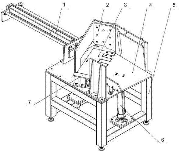
[0008] The present invention will be further described below in conjunction with the accompanying drawings.

[0009] The base 5 is welded with carbon steel sections, and the height-adjustable feet are installed at the bottom. Two flat plates on the base 5 are fixedly turning over push pedal 3 and turning over material receiving plate 4, and turning over pushing pedal 3 and turning over material receiving plate 4 lower ends are connected with turning cylinder 6 respectively.

[0010] The limit buffer plate 2 is connected to the support at the back by 4 groups of guide shafts and linear bearings, and 4 hydraulic buffers are fixed on the support, and the ends of the buffer are pushed against the back side of the limit buffer plate. In this way, when the shaft blank rolls and hits the limit buffer plate, the hydraulic buffer has just played the role of buffer limit.

[0011] The overturning push plate 3 and the overturning material receiving plate 4 are made of 304 stainless stee...


PUM


Abstract

The invention provides a bearing blank automatic turnover mechanism. A turnover push plate and a turnover collection plate are arranged on a base. The turnover push plate and the turnover collection plate are staggered at the intersection. The lower end of the turnover push plate and the lower end of the turnover collection plate are each connected with a turnover air cylinder. A bearing blank inlet is formed in one end of the turnover push plate, and a buffer limiting plate is arranged at the other end of the turnover push plate. The back face of the buffer limiting plate is connected with a buffer. A pushing air cylinder is further arranged on the base. Guide rods are mounted on the two sides of the pushing air cylinder. Hydraulic buffers are mounted on connecting plates at the tail ends of the guide rods. The bearing blank automatic turnover mechanism has the beneficial effects that stable and reliable turnover of a bearing blank is achieved; impacting and bumping are avoided; the continuity and the automation degree in the bearing machining process are improved; and reliability and durability are achieved.

Description

technical field [0001] The invention relates to a bearing processing equipment, in particular to an automatic turning mechanism for a shaft blank. Background technique [0002] During the manufacturing process of bearings, the shaft blank needs to be transferred to the subsequent station for further processing, such as cooling, etc., after undergoing sleeve forging, ring grinding and diameter adjustment. In order to facilitate the transfer, the shaft blank is generally rolled in the launder, that is, the shaft blank is manually placed at one end of the launder, and it is rolled to the other end under the action of gravity. If its next process needs to be connected to the conveyor, the shaft blank cannot be conveyed vertically on the conveyor, so it needs to be turned 90 degrees. At present, the structure of the launder is used to let the shaft blank naturally tip over, but the reliability of natural tipping is poor, and it will have a great impact on the surface of the conv...

Claims


Application Information

Patent Timeline
Patent Type & Authority Applications(China)
IPC IPC(8): B65G47/248
Inventor 王金存包国忱柳东阳
Owner 大连美嘉洛机器人科技有限公司
Why Eureka
Try Eureka