Stilling basin system

A stilling pool and stilling technology, applied in water conservancy projects, sea area projects, coastline protection, etc., can solve the problems of high building strength requirements, limited energy dissipation efficiency, short service life, etc., and achieve low cost, convenient implementation, and use long life effect

Active Publication Date: 2017-12-01
CHONGQING JIAOTONG UNIVERSITY
View PDF4 Cites 3 Cited by
  • Summary
  • Abstract
  • Description
  • Claims
  • Application Information

AI Technical Summary

Problems solved by technology

The energy dissipation efficiency of these existing methods is relatively limited. Usually, a relatively long and large stilling basin needs to be installed, and the building strength required for the water supply flow to hit the energy dissipation part is high, resulting in high implementation costs and short service life.

Method used


Image

  • Stilling basin system
  • Stilling basin system
  • Stilling basin system

Examples


specific Embodiment approach

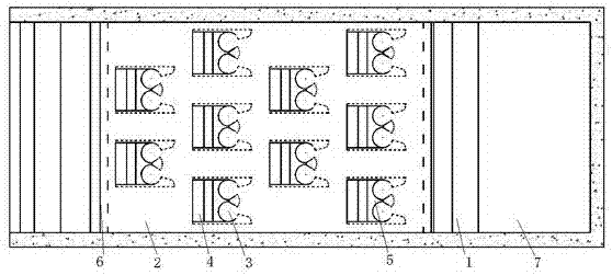
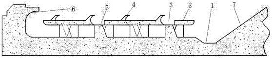
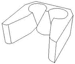
[0033] Specific implementation methods: such as Figure 1-3 As shown, a stilling pool system, including a stilling pool, is characterized in that the water inlet end of the stilling pool is concavely formed with a buffer stilling tank 1, and the height of the bottom surface of the stilling pool in front of the buffer stilling tank 1 is greater than that of the buffer stilling tank. The height of the bottom surface of the force tank, the bottom of the stilling pool in front of the buffer stilling tank 1 is provided with diverter plates 2 at intervals upwards, the rear end of the diverter plate 2 is connected to the front end of the buffer stilling tank, and the diverter plate 2 is in a horizontal state as a whole and is in a horizontal state with the buffer stilling force There is a gap between the bottom surfaces of the stilling pool in front of the groove for the bottom water flow to pass through, and the rear part of the diverter plate 2 is formed with a flow guide structure ...


PUM


Abstract

The invention discloses a stilling basin system, which comprises a stilling basin and is characterized in that the water inlet end of the stilling basin is downwards recessed to from a buffer stilling groove; the height of the bottom surface of the stilling basin positioned in front of the buffer stilling groove is greater than the height of the bottom surface of the buffer stilling groove; flow division plates are upwards arranged on the bottom surface of the stilling basin positioned in front of the buffer stilling groove at intervals; the back end of each flow division plate is connected with the upper side of the front end of the buffer stilling groove; the whole of the flow division plate is in a horizontal state; a gap through which bottom layer water flow passes is formed between the flow division plate and the bottom surface of the buffer stilling groove arranged in front of the buffer stilling groove; and a flow guide structure used for guiding the bottom layer water flow of the flow division plate to upwards move and to realize the collision merging with the upper layer water flow of the flow division plate is formed at the back part of the flow division plate. The stilling basin system has the advantages that the energy carried by the water flow per se is ingeniously used for energy dissipation; and the advantages of implementation convenience, low cost, high energy dissipation efficiency, long service life and the like are realized.

Description

technical field [0001] The invention belongs to the field of river hydropower engineering construction, and in particular relates to a stilling pool system. Background technique [0002] In the construction of water conservancy and hydropower projects, overflow dams are a very common dam shape, such as gate dams, overflow gravity dams, etc. In order to meet the demand of energy dissipation and anti-scouring, it is often necessary to arrange energy dissipation workers behind the overflow dam to reduce the huge kinetic energy of the water flow due to the difference in water level between the upstream and downstream. [0003] Among the common energy dissipation works, the stilling basin is the most common because of its simple structure, convenient implementation and relatively good energy dissipation effect. A stilling basin is a pool-like energy-dissipating facility that can induce an underflow hydraulic jump downstream of a discharge structure. It can quickly change the ra...

Claims


Application Information

Patent Timeline
Patent Type & Authority Applications(China)
IPC IPC(8): E02B8/06
CPCE02B8/06
Inventor 钟亮倪志辉张建梅姜彤廖尚超王振志王舒
Owner CHONGQING JIAOTONG UNIVERSITY
Why Eureka
Try Eureka