
Lifting stand column

A technology for lifting columns and casings, which is applied to belts/chains/gears, mechanical equipment, transmission devices, etc., can solve the problems of troublesome assembly, high cost of lifting columns, and high costs of non-circular tubes, and achieves cost reduction requirements and easy assembly. Effect

Pending Publication Date: 2017-12-01
NINGBO HAISHIKAI DRIVER TECH CO LTD
View PDF6 Cites 6 Cited by
  • Summary
  • Abstract
  • Description
  • Claims
  • Application Information

AI Technical Summary

Problems solved by technology

[0003] The relative expansion and contraction between the inner tube, the middle tube and the outer tube is driven by the lifting of the screw drive assembly, and the movement trajectory between the inner tube, the middle tube and the outer tube is to ensure the relative movement in the axial direction. However, the circumferential direction should be kept relatively fixed and not rotated. In order to ensure that the inner pipe, the middle pipe and the outer pipe do not rotate, the existing lifting columns on the market usually adopt two methods. One is to connect the three pipes It is set as a non-circular tube and then socketed in sequence, but the cost of the non-circular tube is relatively high. The other is to set grooves on the tube walls of the three tubes, and then use mutual positioning to achieve mutual rotation. Obviously These two methods have relatively high requirements on the structure of the pipe fittings, so that the product cost of the lifting column is relatively high, and the assembly is also more troublesome.

Method used


Image

  • Lifting stand column
  • Lifting stand column
  • Lifting stand column

Examples


Embodiment 1

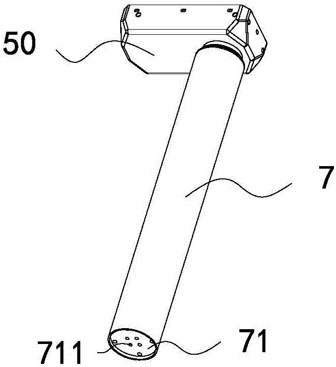
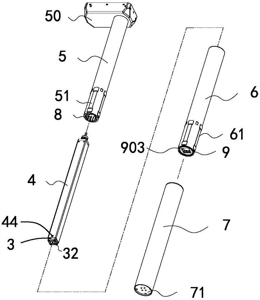
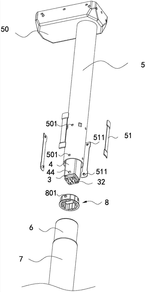
[0041] Such as Figure 1 to Figure 6 As shown, the present embodiment is a lifting column, which includes an inner tube 5, a middle tube 6, and an outer tube 7 that are sequentially set from the inside to the outside, wherein the upper end of the inner tube 5 is fixedly connected to the bottom shell 50, and the inside of the bottom shell 50 is installed with drive, drive in Figures 1 to 6 Not shown in the figure, the driver usually includes a motor and a reduction mechanism. The driver is connected with a screw drive assembly. The principle of the screw drive assembly is to use the drive screw 2 to drive the drive nut to move axially, thereby driving the first casing 3 Move relative to the axial direction with the second sleeve 4, and the specific structure is described below.

[0042] The bottom case 50 includes a box body and a box cover. The box cover is fastened to the opening of the box body so that the bottom case 50 has an accommodating space for accommodating the dri...


PUM


Abstract

The invention discloses a lifting stand column and belongs to the technical field of linear driving. The lifting stand column comprises an inner tube, a medium tube and an outer tube which are sequentially sleeved from inside to outside, wherein a bottom shell is fixedly connected at the upper end of the inner tube; a driver is arranged in the bottom shell and connected with a screw rod drive assembly; the inner tube is sleeved outside the screw rod drive assembly; the screw rod drive assembly comprises a first sleeve tube and a second sleeve tube which is sleeved outside the first sleeve tube; the first sleeve tube and the second sleeve tube can be relatively moved in the axial direction and maintain the relative fixation in the circumferential direction; the lower end of the outer tube is fixedly connected with the lower end of the first sleeve tube; a guide sleeve for maintaining the relative fixation of the inner tube and the second sleeve tube in the circumferential direction is arranged between the inner tube and the second sleeve tube; and a connecting component is fixedly connected between the medium tube and the second sleeve tube to maintain the relative fixation of the medium tube and the second sleeve tube in the circumferential direction. The lifting stand column disclosed by the invention has the advantages that the manufacturing process is simpler and the product cost is reduced.

Description

【Technical field】 [0001] The invention relates to a lifting column and belongs to the technical field of linear transmission. 【Background technique】 [0002] Electric lifting columns are widely used in household, medical and other fields. The pipe body of the existing electric lifting columns generally includes an inner tube, a middle tube, and an outer tube that are sequentially fitted from the inside to the outside. The upper end of the inner tube is fixedly connected with a bottom shell, and the bottom The driver provided in the shell is connected to the screw drive assembly by drive transmission. The drive screw assembly usually includes a first sleeve and a second sleeve, and the first sleeve and the second sleeve are driven by a screw and a nut. The principle is used to achieve relative movement in the axial direction, while the first sleeve and the second sleeve cannot rotate relative to each other in the circumferential direction. [0003] The relative expansion and...

Claims


Application Information

Patent Timeline
Patent Type & Authority Applications(China)
IPC IPC(8): F16H25/24F16H25/20
CPCF16H25/20F16H25/24F16H2025/2062
Inventor 龚旭良张东行
Owner NINGBO HAISHIKAI DRIVER TECH CO LTD
Learn More