Supercharge Your Innovation With Domain-Expert AI Agents!

A kind of valve quick turning device

A technology of fast turning and rotating devices, which is applied in the direction of valve devices, valve operation/release devices, valve details, etc. It can solve the problems of valves not being used normally, cumbersome and inconvenient, and easy to rust valves, so as to achieve convenient and fast rotating valves, Simple operation effect

Active Publication Date: 2019-02-12
CAMBRIDGE VALVE IND GRP CO LTD
View PDF5 Cites 0 Cited by
  • Summary
  • Abstract
  • Description
  • Claims
  • Application Information

AI Technical Summary

Problems solved by technology

[0005] In order to overcome that some valves on the pipeline do not need to be used frequently, the valves are prone to rust if they are not used for a long time, and the valves cannot be used normally. In order to keep them in normal use, people need to rotate the valves at intervals , this process is not only cumbersome and inconvenient, but also time-consuming and labor-intensive. The technical problem to be solved by the present invention is to provide a valve quick-turning device that is convenient, fast, and easy to operate.

Method used


Image

  • A kind of valve quick turning device
  • A kind of valve quick turning device
  • A kind of valve quick turning device

Examples


Embodiment 1

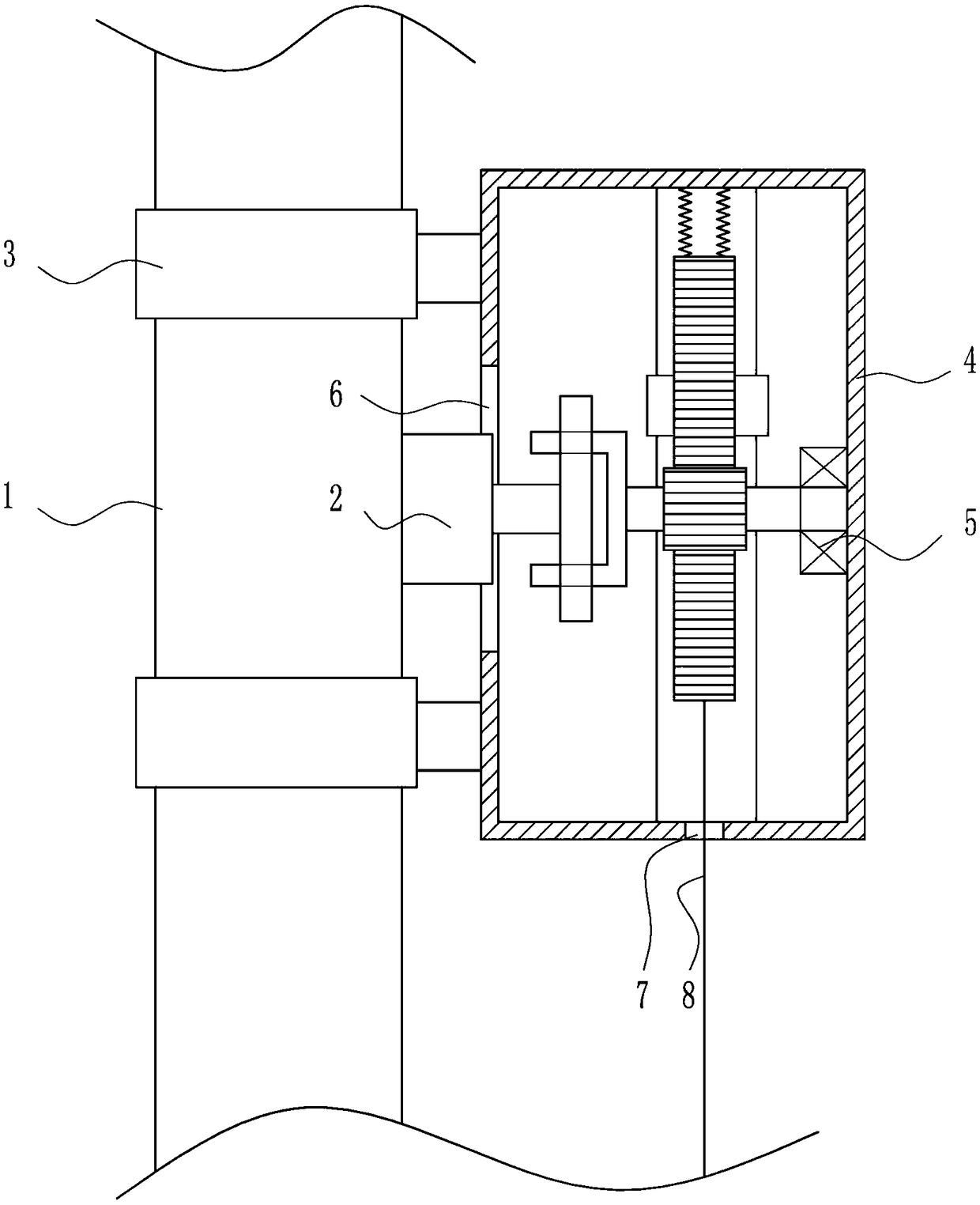
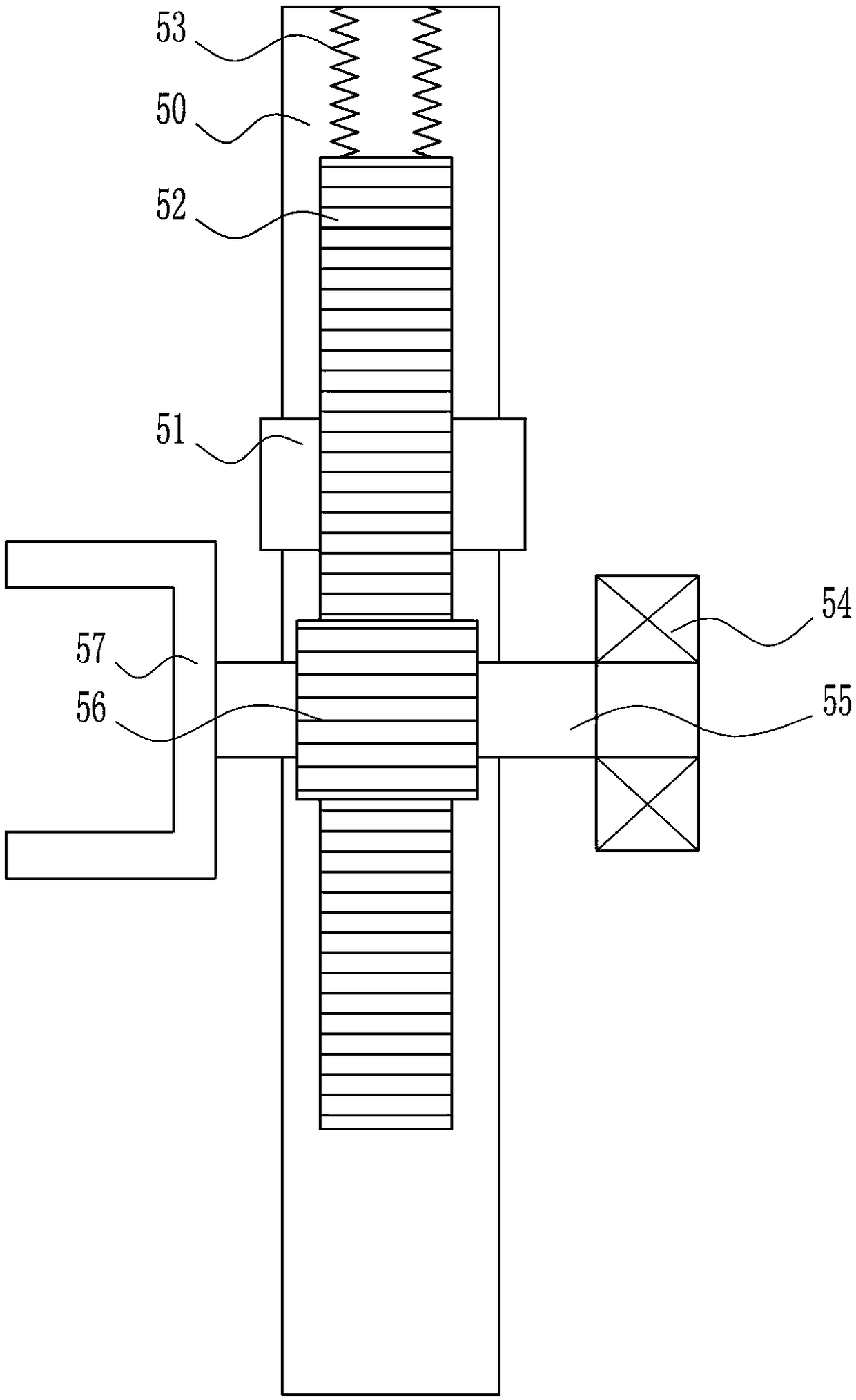
[0031] A valve quick turn device, such as Figure 1-5 As shown, it includes a pipeline 1, a valve 2, a clamping device 3, a first shell 4, a rotating device 5 and a pull cord 8, the right side of the pipeline 1 is provided with a valve 2, and the pipeline 1 is provided with a clamping device 3 for clamping The device 3 is located on the upper and lower sides of the valve 2, the right side of the clamping device 3 is provided with a first housing 4, the first housing 4 is provided with a rotating device 5, the left side of the first housing 4 has an opening 6, and the valve 2 passes through the opening 6. A first through hole 7 is opened at the bottom of the first housing 4 , and a pull rope 8 is connected to the bottom of the rotating device 5 , and the pull rope 8 passes through the first through hole 7 .

Embodiment 2

[0033] A valve quick turn device, such as Figure 1-5As shown, it includes a pipeline 1, a valve 2, a clamping device 3, a first shell 4, a rotating device 5 and a pull cord 8, the right side of the pipeline 1 is provided with a valve 2, and the pipeline 1 is provided with a clamping device 3 for clamping The device 3 is located on the upper and lower sides of the valve 2, the right side of the clamping device 3 is provided with a first housing 4, the first housing 4 is provided with a rotating device 5, the left side of the first housing 4 has an opening 6, and the valve 2 passes through the opening 6. A first through hole 7 is opened at the bottom of the first housing 4 , and a pull rope 8 is connected to the bottom of the rotating device 5 , and the pull rope 8 passes through the first through hole 7 .

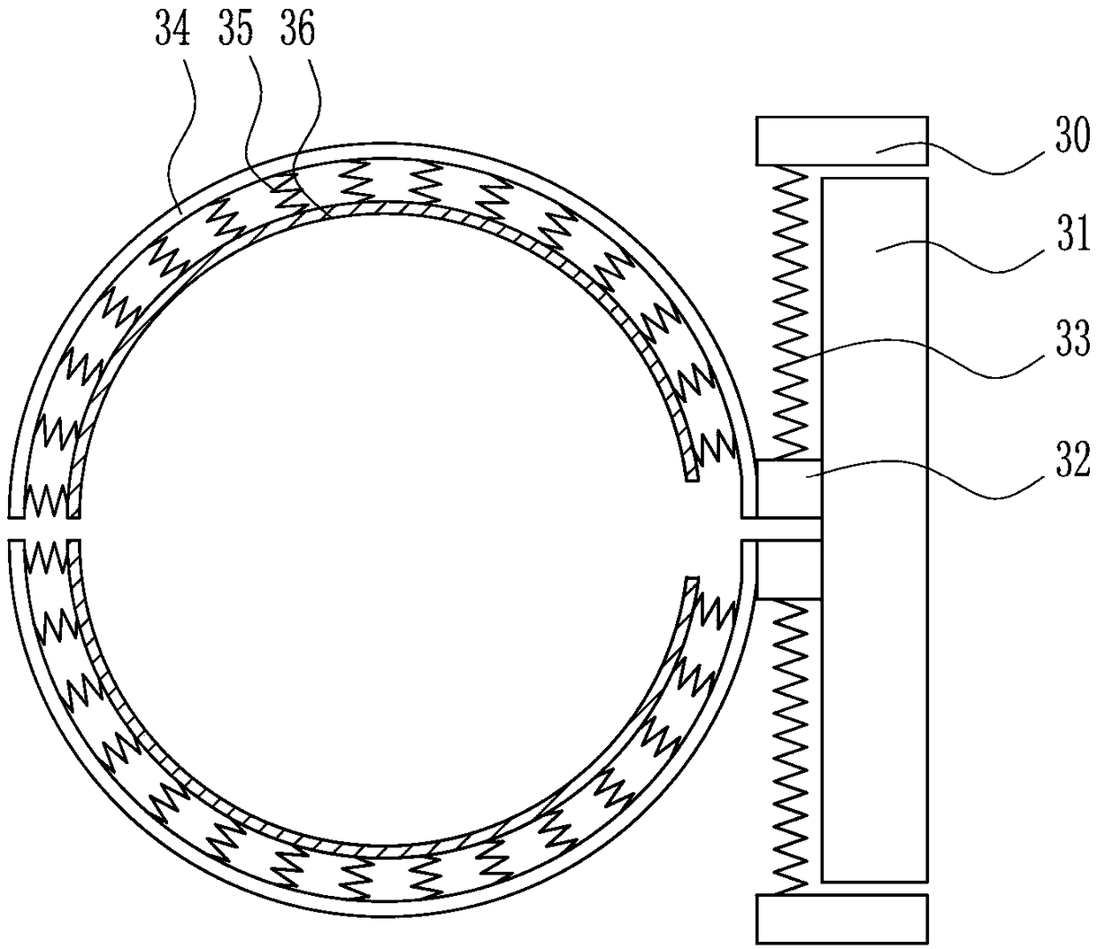
[0034] The clamping device 3 includes a fixed rod 30, a first slide rail 31, a first slider 32, a first spring 33, a clamp rod 34, a second spring 35 and a rubber pad 36, a...

Embodiment 3

[0036] A valve quick turn device, such as Figure 1-5 As shown, it includes a pipeline 1, a valve 2, a clamping device 3, a first shell 4, a rotating device 5 and a pull cord 8, the right side of the pipeline 1 is provided with a valve 2, and the pipeline 1 is provided with a clamping device 3 for clamping The device 3 is located on the upper and lower sides of the valve 2, the right side of the clamping device 3 is provided with a first housing 4, the first housing 4 is provided with a rotating device 5, the left side of the first housing 4 has an opening 6, and the valve 2 passes through the opening 6. A first through hole 7 is opened at the bottom of the first housing 4 , and a pull rope 8 is connected to the bottom of the rotating device 5 , and the pull rope 8 passes through the first through hole 7 .

[0037] The clamping device 3 includes a fixed rod 30, a first slide rail 31, a first slider 32, a first spring 33, a clamp rod 34, a second spring 35 and a rubber pad 36, ...


PUM


Abstract

The invention relates to a rotating device, in particular to a valve rapid rotating device. According to the technical aims, the valve rapid rotating device which enables valve rotation to be convenient and rapid, and is easy to operate is provided. In order to achieve the technical aims, the valve rapid rotating device comprises a pipeline and other parts. A valve is arranged on the right side of the pipeline, and clamping devices are arranged on the pipeline and located on the upper side and the lower side of the valve. A first shell is arranged on the right sides of the clamping devices, and a rotating device is arranged in the first shell. An opening is formed in the left side of the first shell, and the valve passes through the opening. A first through hole is formed in the bottom of the first shell, and a pull rope is connected to the bottom of the rotating device, and passes through the first through hole. The valve rapid rotating device achieves the effects that valve rotation is convenient and rapid, and operation is easy. The pipeline can be protected by second springs, so that the pipeline is not prone to being damaged due to clamping. the friction between clamping rods and the pipeline can be increased by rubber gaskets.

Description

technical field [0001] The invention relates to a rotating device, in particular to a fast rotating device for a valve. Background technique [0002] Valves are the control components in the fluid delivery system. They have the functions of cut-off, adjustment, flow diversion, reverse flow prevention, pressure stabilization, flow diversion or overflow pressure relief. Valves used in fluid control systems range from the simplest cut-off valve to extremely complex There are various types and specifications of valves used in the automatic control system. Valves can be used to control the flow of various types of fluids such as air, water, steam, various corrosive media, mud, oil, liquid metal and radioactive media. [0003] Some valves on the pipeline do not need to be used frequently. The valves are prone to rust if they are not used for a long time, which will cause the valves to fail to work normally. In order to keep them in normal use, people need to turn the valves at in...

Claims


Application Information

Patent Timeline
Patent Type & Authority Patents(China)
IPC IPC(8): F16K31/54F16K31/46F16L55/07
CPCF16K31/465F16K31/54F16L55/07
Inventor 沈婉珍
Owner CAMBRIDGE VALVE IND GRP CO LTD
Features
  • R&D
  • Intellectual Property
  • Life Sciences
  • Materials
  • Tech Scout
  • Unparalleled Data Quality
  • Higher Quality Content
  • 60% Fewer Hallucinations
Learn More