

Switch matrix and self-check method thereof
A technology of switch matrix and self-inspection process, which is applied in the direction of circuit breaker testing, measuring device casing, etc., and can solve problems such as inability to overhaul, waste, and inability to achieve fault warning
- Summary
- Abstract
- Description
- Claims
- Application Information
AI Technical Summary
Problems solved by technology
Method used
Image

Examples
Embodiment Construction
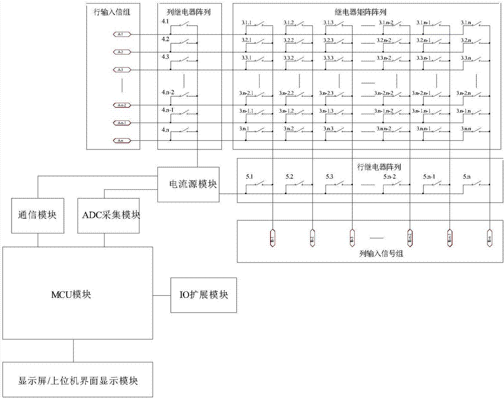
[0039] see figure 1 , a switch matrix, including a row input signal group, a column input signal group, a relay matrix array, a column relay array, a row relay array, a current source module, an MCU module, a communication module, an ADC acquisition module, and a display screen / upper interface module; the display screen / upper position interface module, ADC acquisition module, and communication module are respectively connected to the MCU module; the ADC acquisition module and communication module are respectively connected to the current source module; the column relay The array and the row relay array are respectively connected to the current source module; each relay of the column relay array selects a row of relays of the relay matrix array to connect; each relay of the row relay array selects a relay of the relay matrix array respectively A column of relays is connected; each input signal of the row input signal group is connected to a relay in the column relay array, and ...
PUM
 Abstract
Description
Claims
Application Information