A three-layer network interface device and mapping method

A technology of an interface device and a mapping method, applied in the field of communication, can solve problems such as inability to meet product requirements and cost sensitivity

Active Publication Date: 2021-03-19
深圳市中航比特通讯技术股份有限公司
View PDF10 Cites 0 Cited by
  • Summary
  • Abstract
  • Description
  • Claims
  • Application Information

AI Technical Summary

Problems solved by technology

Small communication equipment is sensitive to cost, the above method cannot meet the product demand

Method used


Image

  • A three-layer network interface device and mapping method
  • A three-layer network interface device and mapping method

Examples


Embodiment Construction

[0012] In order to make the object, technical solution and advantages of the present invention clearer, the present invention will be further described in detail below in conjunction with the accompanying drawings and embodiments. It should be understood that the specific embodiments described here are only used to explain the present invention, not to limit the present invention.

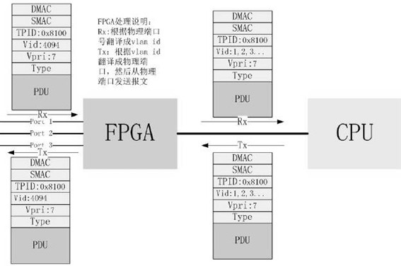
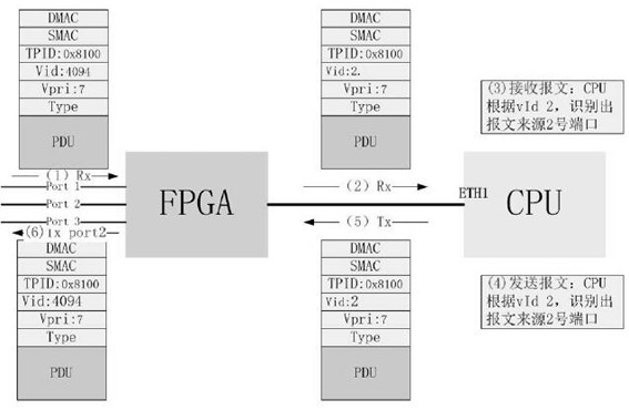
[0013] see Figure 1-2 , figure 1 is a schematic diagram of three-layer network interface mapping in the present invention, figure 2 It is a schematic diagram of the mapping process between physical port 2 and a Layer 3 network interface.

[0014] A three-layer network interface device and mapping method, including CPU, hardware logic FPGA and several physical optical ports, a network interface of the CPU is connected with hardware logic FPGA, and the hardware logic FPGA is connected with several physical optical ports, Described hardware logic FPGA is responsible for extracting / inserting packe...


PUM


Abstract

The invention relates to a three-layer network interface device and a mapping method, including a CPU, a hardware logic FPGA and several physical optical ports, a network interface of the CPU is connected to a hardware logic FPGA, and the hardware logic FPGA is connected to several physical optical ports. Ports are connected, and the hardware logic FPGA is responsible for extracting / inserting packet messages from the physical ports. Compared with the prior art, the present invention has the following outstanding features and significant progress: in communication equipment, generally a physical service port will be connected inside the equipment. Map a network port. Such a design greatly increases the cost of the equipment, especially on miniaturized equipment, these cost consumptions are even more expensive. Based on this patent, a communication device only needs one network interface on the internal CPU of the device, and can correspond to multiple physical ports, which greatly reduces hardware costs. The cost reduction becomes more pronounced as the number of ports increases.

Description

technical field [0001] The invention relates to the field of communication technology, in particular to a three-layer network interface device and a mapping method. Background technique [0002] In a communication device, it is generally necessary to map a physical interface to an IP network to form a layer-3 network interface. The common way to implement similar problems is that in large-scale communication equipment, the physical ports are usually mapped to several network ports of the internal CPU (central processing unit) of the equipment. Among them, the hardware port is responsible for the extraction and insertion of packet packets, and the network port of the CPU is responsible for the Layer 3 network functions, such as route learning, or learning the MAC address of the remote Layer 3 interface through ARP. In this method, the relationship between the physical interface and the layer-3 network interface is a one-to-one correspondence. It has certain requirements on ...

Claims


Application Information

Patent Timeline
Patent Type & Authority Patents(China)
IPC IPC(8): H04L29/12H04L12/935H04L29/10H04L12/46H04L49/111
CPCH04L49/3009H04L12/4641H04L69/32H04L2101/677
Inventor 冉隆成
Owner 深圳市中航比特通讯技术股份有限公司
Why Eureka
Try Eureka