
a mixer truck

A technology for mixing trucks and aggregates, which is applied to unloading devices, cement mixing devices, clay preparation devices, etc., can solve the problems of slowing down the construction progress, easy splashing of discharge materials, and high use costs, and achieves speeding up the construction progress. , Improve the discharge efficiency, improve the effect of feeding speed

Active Publication Date: 2019-09-10
TANGSHAN TANGHONG HEAVY IND SPECIAL PURPOSE VEHICLE CO LTD
View PDF7 Cites 0 Cited by
  • Summary
  • Abstract
  • Description
  • Claims
  • Application Information

AI Technical Summary

Problems solved by technology

[0002] Concrete is one of the raw materials often used in bridge foundation construction or maintenance. It is made by mixing cement and sand with water. It is mainly used for laying bridge pavement and pouring during bridge foundation construction. In traditional technology, concrete mixing Generally, manual mixing is used, and the mixing is not uniform. For some bridge constructions with tight construction schedules and multiple people working at the same time, the mixing efficiency is low, it is difficult to supply what is needed, and the construction progress is slowed down. There are also automatic mixing equipment in the prior art. However, its use cost is high, the operation is complicated, and it is easy to splash when discharging, which causes waste and is extremely difficult to clean. There are major disadvantages and need to be improved.

Method used


Image

  • a mixer truck
  • a mixer truck
  • a mixer truck

Examples


Embodiment Construction

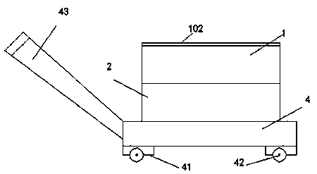
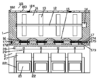
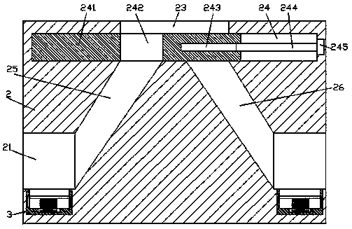
[0024] Such as Figure 1-Figure 6 As shown, a mixing cart of the present invention includes a mixing part 1, a feeding part 2 arranged at the bottom of the mixing part 1, and a frame body 4 arranged at the bottom of the feeding part 2. The bottom end surface of the material part 2 is fixedly connected with the top surface of the frame body 4, corner posts 41 are arranged on the four corners of the bottom of the frame body 4, and rollers 42 are provided at the bottom of each corner post 41, thereby facilitating movement or transportation , the left end surface of the frame body 4 is fixed with an oblique push handle 43, the mixing part 1 is provided with a silo 11, and the bottom of the silo 11 is provided with multiple groups of bucket-shaped grooves 15, and each bucket-shaped The bottom of the groove 15 is provided with a mouth 16, and the mouth 16 is provided with a first sliding groove 17 passing through the mouth 16 and extending to the left and right sides, and the first ...


PUM


Abstract

The invention discloses a mixing truck. The mixing truck comprises a mixing part, a discharging part and a frame body, wherein the discharging part is arranged at the bottom of the mixing part, and the frame body is arranged at the bottom of the discharging part; the bottom end surface of the discharging part is fixedly connected to the top end surface of the frame body; corner posts are arranged at the four corners of the bottom of the frame body; a rolling wheel is arranged at the bottom of each corner post; an oblique pushing handle is fixedly arranged on the left end surface of the frame body; a stock bin is arranged in the mixing part; a plurality of groups of funnel-shaped grooves are formed in the bottom of the stock bin; an opening part is formed in the bottom of each funnel-shaped groove; first sliding grooves which penetrate through the opening parts and extend towards the left side and the right side are formed in the opening parts; a first sliding part is arranged in the first sliding grooves; groove holes are formed in the first sliding part; a first threaded hole is formed in the right side of the first sliding part; and a first spiral rod is connected to threads in the first threaded hole in a matched mode and is connected to a first motor. The mixing truck has the advantages of being simple in structure, reasonable in design and simple and convenient to operate, automatic mixing and automatic discharging can be realized simultaneously, the working efficiency can be improved, the waste can be reduced, and the cleanliness can be ensured.

Description

technical field [0001] The invention relates to the technical field of bridge equipment, in particular to a mixer truck. Background technique [0002] Concrete is one of the raw materials often used in bridge foundation construction or maintenance. It is made by mixing cement and sand with water. It is mainly used for laying bridge pavement and pouring during bridge foundation construction. In traditional technology, concrete mixing Generally, manual mixing is used, and the mixing is not uniform. For some bridge constructions with tight construction schedules and multiple people working at the same time, the mixing efficiency is low, it is difficult to supply what is needed, and the construction progress is slowed down. There are also automatic mixing equipment in the prior art. However, its use cost is high, the operation is complicated, and it is easy to splash when discharging, which causes waste and is extremely difficult to clean. There are major drawbacks and need to b...

Claims


Application Information

Patent Timeline
Patent Type & Authority Patents(China)
IPC IPC(8): B28C5/14B28C5/08B28C7/16
Inventor 陈亚利
Owner TANGSHAN TANGHONG HEAVY IND SPECIAL PURPOSE VEHICLE CO LTD
Learn More