Stamping die guiding and positioning mechanism

A technology of guiding positioning and stamping dies, which is applied in the direction of forming tools, manufacturing tools, metal processing equipment, etc., and can solve the problem of low positioning accuracy

Inactive Publication Date: 2017-12-08
芜湖博康新材料技术有限公司
View PDF10 Cites 2 Cited by
  • Summary
  • Abstract
  • Description
  • Claims
  • Application Information

AI Technical Summary

Problems solved by technology

[0002] The current stamping die is the upper mold frame with the upper template and the lower template on the lower mold frame. The stamping die is used to stamp the plate through the upper template. During the stamping process, the shear force of the plate reaction will make the upper The mold base or the lower mold base is subjected to the force of lateral displacement. For stamping dies with high precision requirements, this lateral displacement must be avoided. Therefore, the guiding positioning of high-precision stamping dies has become the core issue to be considered. The traditional method is to pass The way of guide column and guide hole prevents the occurrence of lateral displacement, and the guide positioning accuracy is low

Method used


Image

  • Stamping die guiding and positioning mechanism
  • Stamping die guiding and positioning mechanism
  • Stamping die guiding and positioning mechanism

Examples


Embodiment 1

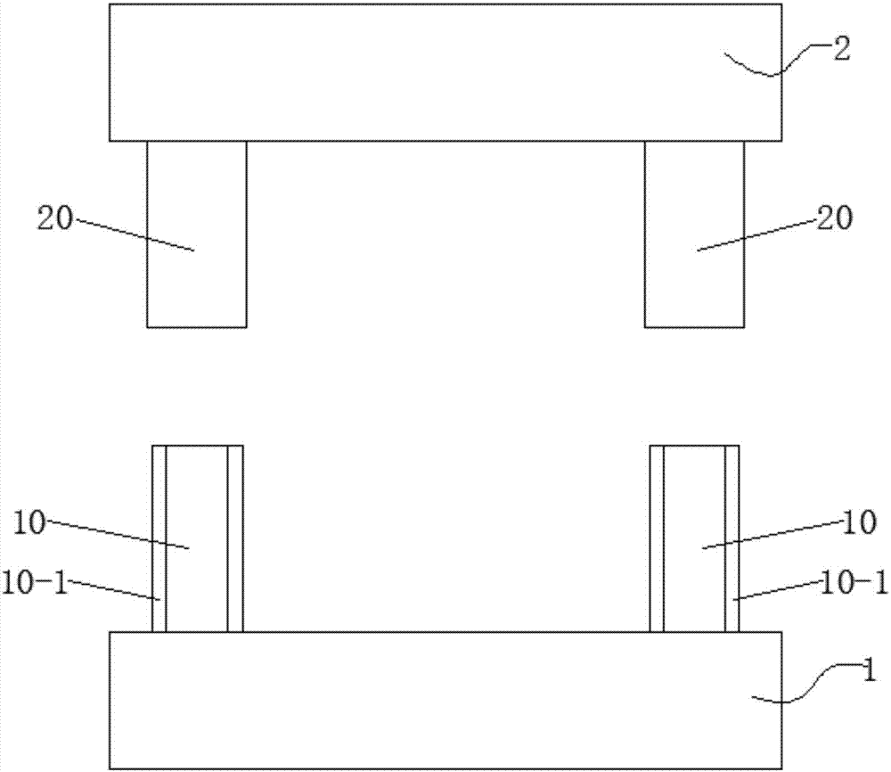
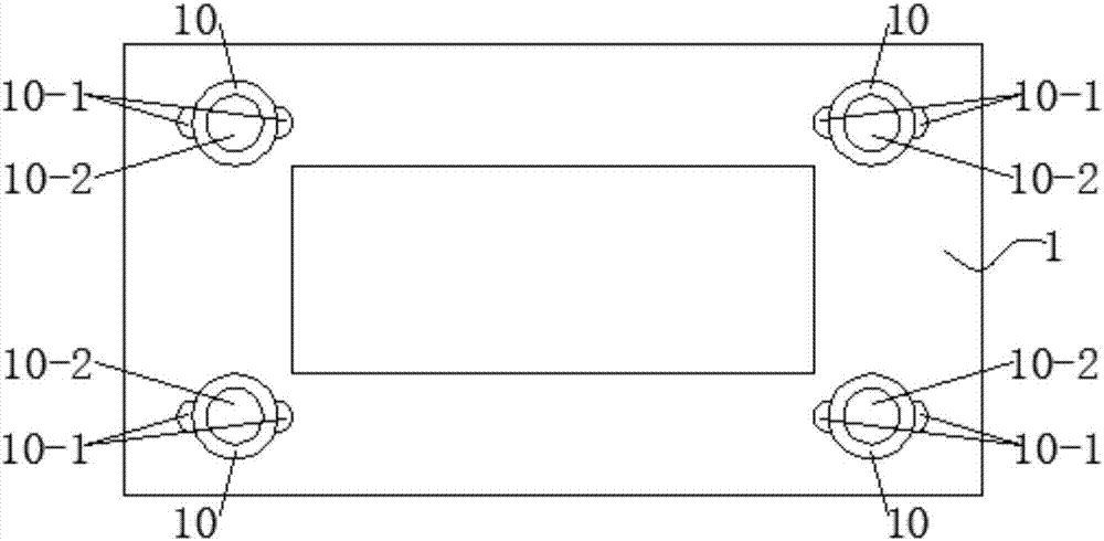
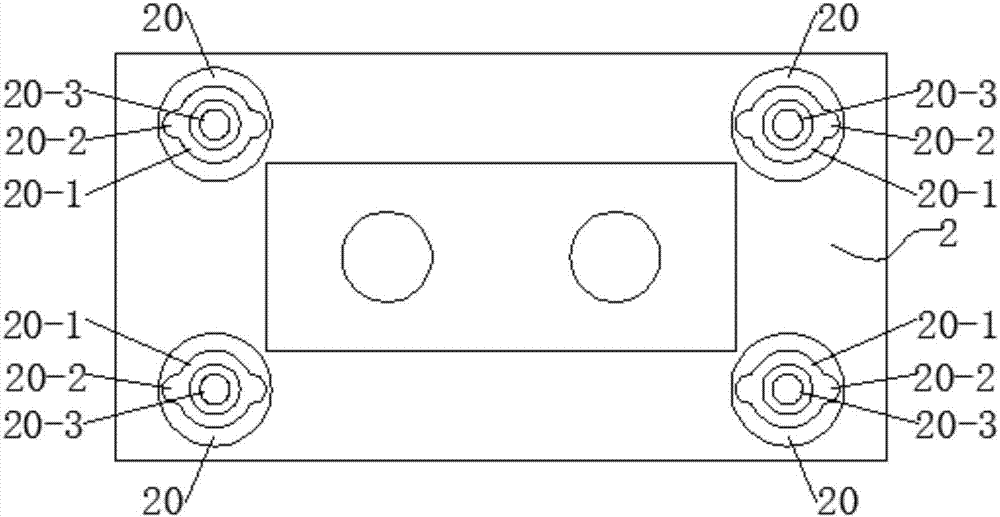
[0026] The stamping die guide positioning mechanism, when the upper mold base 2 and the lower mold base 1 are closed, the guide rod 20-3 on the upper mold base 2 is inserted into the positioning hole 10 in the positioning sleeve 10 on the lower mold base 1 from top to bottom In -2, the diameter of the guide rod 20-3 is the same as the diameter of the positioning hole 10-2, so that the positioning accuracy can be improved by the axis of the positioning sleeve 10 being coaxial with the axis of the guide rod 20-3.

Embodiment 2

[0028] During the clamping process of the upper mold base 2 and the lower mold base 1, the guide groove 20-2 on the inner wall of the guide sleeve 20 is inserted into the positioning bar 10-1 on the outer wall of the positioning sleeve 10 from top to bottom, and passes through a positioning hole 10-1. 2 axes and the axes of two positioning strips 10-1 are co-linear with the axes of a guide rod 20-3 and two guide grooves 20-2 respectively, limiting the lateral displacement of the upper mold frame 2 and the lower mold frame 1, improving In order to improve the precision of the guiding and positioning of the stamping die, avoid the lateral displacement between the upper mold frame 2 and the lower mold frame 1.

[0029] The front end of the guide rod 20-3 has a taper to realize the smoothness of mold clamping; one end of the guide rod 20-3 is provided with an external thread, and the guide rod 20-3 is connected with the upper mold frame 2 through the external thread to ensure The ...


PUM


Abstract

The invention discloses a stamping die guiding and positioning mechanism which comprises a lower die frame and an upper die frame. Four corners of the lower die frame are each provided with a positioning sleeve, the outer wall of each positioning sleeve is provided with two positioning strips which are symmetrically arranged by 180 degrees, and each positioning sleeve is internally provided with a positioning hole. Four corners of the upper die frame are each provided with a guiding sleeve, and each guiding sleeve is internally provided with a guiding hole; the inner wall of each guiding sleeve is provided with two guiding slots which are symmetrically arranged by 180 degrees, and each guiding hole is internally provided with a guiding rod; and each guiding rod is connected with the upper die frame in a threaded manner, and the diameter of each guiding rod is the same as that of the corresponding positioning hole. By means of the stamping die guiding and positioning mechanism, the guiding and positioning precision of a stamping die is improved, and the horizontal displacement generated between the upper die frame and the lower die frame is avoided.

Description

technical field [0001] The invention belongs to the technical field of mold positioning and guiding, in particular, the invention relates to a guiding and positioning mechanism for stamping dies. Background technique [0002] The current stamping die is the upper mold frame with the upper template and the lower template on the lower mold frame. The stamping die is used to stamp the plate through the upper template. During the stamping process, the shear force of the plate reaction will make the upper The mold base or the lower mold base is subjected to the force of lateral displacement. For stamping dies with high precision requirements, this lateral displacement must be avoided. Therefore, the guiding positioning of high-precision stamping dies has become the core issue to be considered. The traditional method is to pass The way of guide column and guide hole prevents the occurrence of lateral displacement, and the guide positioning accuracy is low Contents of the inventi...

Claims


Application Information

Patent Timeline
Patent Type & Authority Applications(China)
IPC IPC(8): B21D37/12B21D37/01
CPCB21D37/12B21D37/01
Inventor 朱忠友冯明英
Owner 芜湖博康新材料技术有限公司
Why Eureka
Try Eureka