Vision measurement method used for overall motion tracking of rotating object

A technology of motion tracking and visual measurement, applied in the field of three-dimensional measurement, which can solve problems such as difficult matching of sub-region rotation angles

Active Publication Date: 2017-12-08
XI AN JIAOTONG UNIV
View PDF6 Cites 25 Cited by
  • Summary
  • Abstract
  • Description
  • Claims
  • Application Information

AI Technical Summary

Problems solved by technology

Use the detected marker points to rotate and transform the speckle images or speckle sub-areas collected before and after, and then search and

Method used


Image

  • Vision measurement method used for overall motion tracking of rotating object
  • Vision measurement method used for overall motion tracking of rotating object
  • Vision measurement method used for overall motion tracking of rotating object

Examples


Embodiment Construction

[0070] For the method involved in this disclosure, an important application is to measure the vibration and deformation of aerodynamic blades such as wind blades, propellers, and rotors during rotation. Therefore, the embodiments of this disclosure take the ventilation fan as the measurement object and describe the implementation of the entire measurement. process.

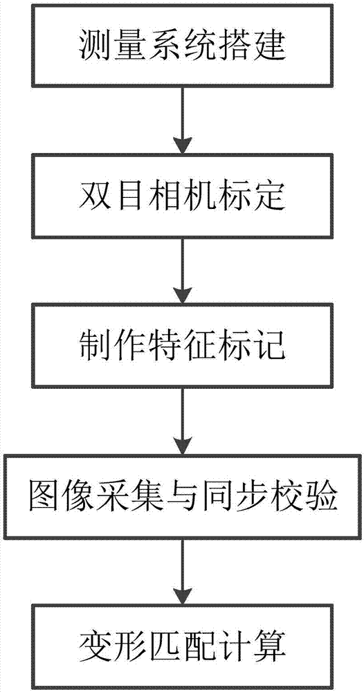
[0071] In one embodiment, a measurement process of rotation tracking is provided, and the sequential steps include measurement system construction -> binocular camera calibration -> making feature marks -> image acquisition and synchronization verification -> deformation matching calculation, such as figure 1 shown. in:

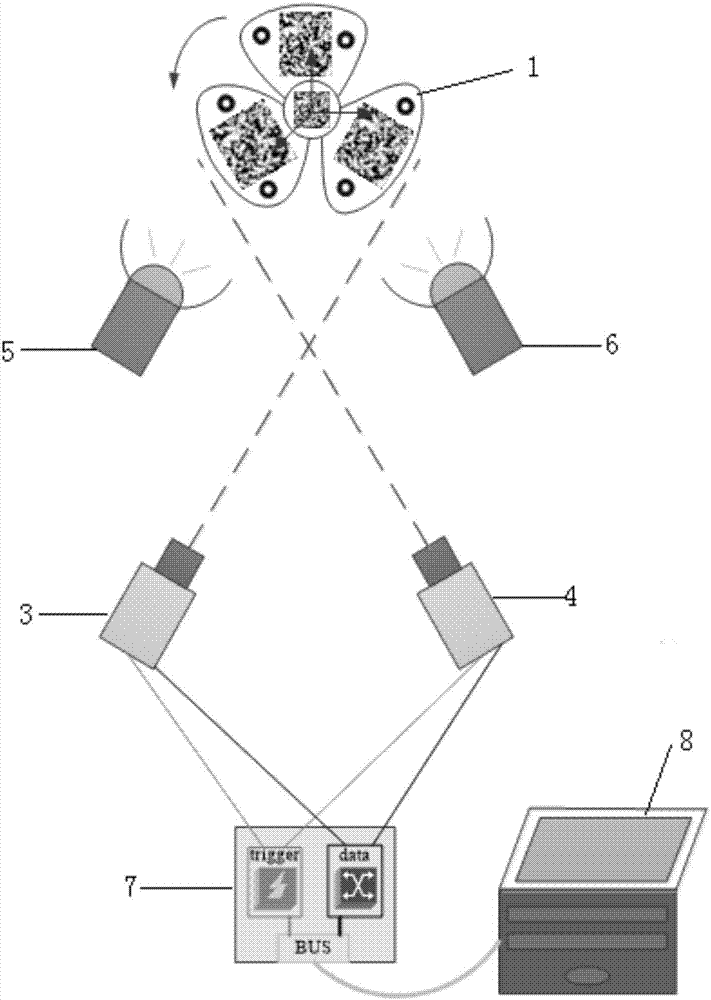
[0072] When constructing the measurement system, figure 2 A measurement system scheme is illustrated. The measurement object is the propeller (1), and the external hardware used mainly includes high-power LEDs (5, 6), two industrial cameras or high-speed cameras (3, 4), a synchronous trigger ...


PUM


Abstract

The invention relates to a vision measurement method used for overall motion tracking of a rotating object. The method combines binocular vision and a digital image correlation method. Speckles are sprayed on the surface of the measured object, and a small number of mark points are attached. The rotation parameters of the center coordinate of a mark point image before and after solving are used to carry out corresponding rotation transformation on speckle images or subsegment sets, wherein the speckle images or subsegment sets are collected before and after. Similar subsegments are searched and matched. The problem of difficult matching caused by large subsegment rotation angle is solved. According to the method provided by the invention, the space coordinate of any position on the feature surface in each state can be accurately acquired to realize tracking and deformation measurement.

Description

technical field [0001] The disclosure relates to the problem of full-field motion tracking and deformation measurement in the field of three-dimensional measurement, and in particular to a binocular vision measurement method for rotating objects. Background technique [0002] Motion tracking and deformation measurement of rotating objects is a problem worthy of attention. For example, in the fault detection of rotating machinery such as large wind blades or propellers, it is of great significance to judge the performance of blade materials under high torque and high speed. However, the contact sensors commonly used at this stage are difficult to effectively cope with this measurement requirement. On the one hand, due to the problem of lead wires, the sensor is not easy to arrange on large or high-speed rotating blades; on the other hand, the observation points established by the sensor are limited, and the full-field displacement and deformation of any position of the entire...

Claims


Application Information

Patent Timeline
IPC IPC(8): G06T7/246G06T7/73G06T7/00G06T3/60G01N21/86G01B11/16
CPCG01B11/16G01N21/86G01N2021/8645G06T3/608G06T7/001G06T7/248G06T7/74G06T2207/10016G06T2207/30108
Inventor 梁晋千勃兴李文攀徐劲澜孟繁昌赵鹏亮张桁维
Owner XI AN JIAOTONG UNIV
Why Eureka
Try Eureka