

Novel environmental-protection dust removal apparatus
A dust-removing device and environmental protection technology, applied in coupling devices, parts of connecting devices, devices to prevent contact with live contacts, etc., can solve problems such as deteriorating workshop environment and air, user safety accidents, pollution, etc. performance and accuracy, preventing electric shock accidents, and reducing the cost of use
- Summary
- Abstract
- Description
- Claims
- Application Information
AI Technical Summary
Problems solved by technology
Method used
Image

Examples
Embodiment Construction
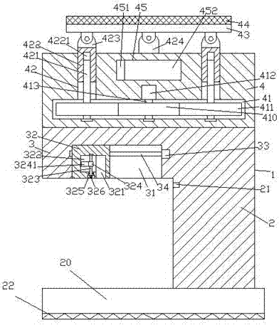
[0027] Such as Figure 1-Figure 9As shown, a novel environment-friendly dust removal device of the present invention includes a column body 1, a light energy conversion part 4 fixedly installed on the top end surface of the column body 1, and an electrical coupling head 5. The column body 1 is composed of a load-bearing part 2 and The pushing part 3 is assembled, and the bottom end surface of the pushing part 3 is provided with a pushing groove 31, and the first stud 34 elongated from left to right is arranged in the pushing groove 31, and the right side end of the first stud 34 is connected to the The first motor 33 is connected, and the first motor 33 is provided with a supporting device. The supporting device includes a shock-reducing flat plate 332 and a heat-absorbing sheet 331. Cooperate with the connected push block 32, the push block 32 is provided with a first container 322, and the push block 32 on the right side of the first container 322 is provided with a lock who...
PUM
 Abstract
Description
Claims
Application Information