Novel bus frame
A busbar frame, a new type of technology, applied in the direction of fully enclosed busbar devices, busbar/line layout, etc., can solve the problems of expansion or maintenance troubles, high assembly process requirements, difficult assembly, etc., to achieve convenient and fast installation, convenient expansion and Cutting, making up for effects with height differences
- Summary
- Abstract
- Description
- Claims
- Application Information
AI Technical Summary
Problems solved by technology
Method used
Image
Examples
Embodiment 1
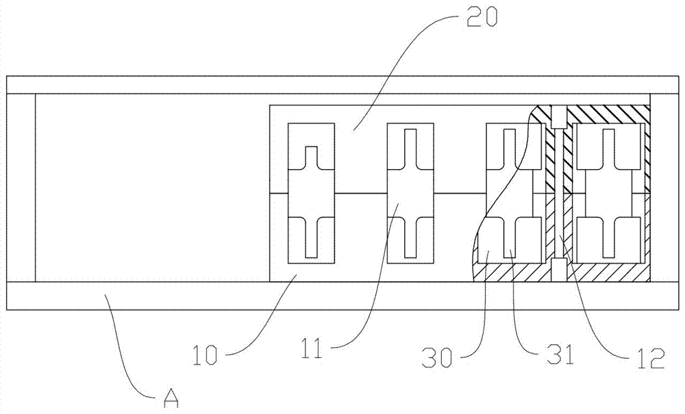
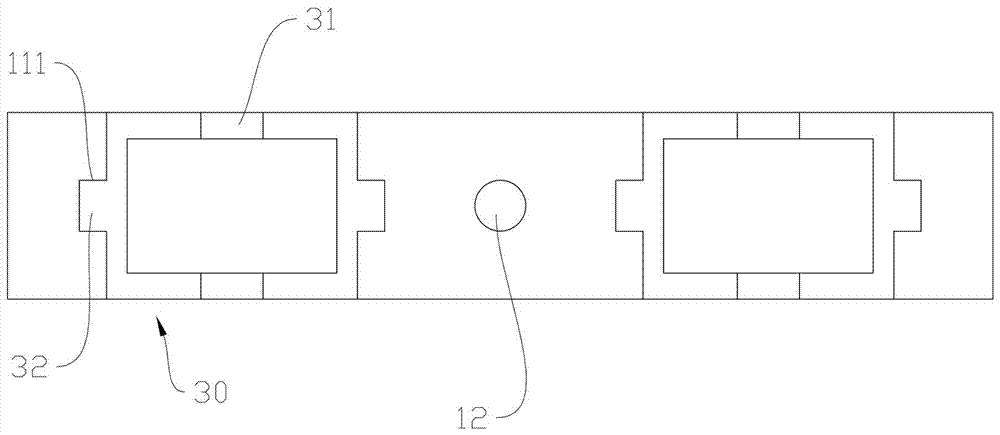
[0029] Example 1: as Figure 1-2 As shown, a new type of busbar frame is erected on the busbar bridge A of the power distribution cabinet. The new type of busbar frame includes a vertically joined bottom frame 10 and a top frame 20. The bottom frame 10 and the top frame 20 have the same structure and are arranged in a mirror image; The frame 10 and the top frame 20 are provided with at least one opening slot 11 corresponding to the position on the opposite joint surfaces. The opening slot 11 is provided with a vertically slidable clamping block 30. Card holes 31 with suitable widths.
[0030] Two vertical groove walls of the opening slot 11 are provided with sliding grooves 111 , and the clamping block 30 is provided with a protrusion 32 which is slidably matched with the sliding grooves 111 .
[0031] The bottom frame 10 is integrally formed, the opening grooves 11 on the bottom frame 10 are arranged in parallel and spaced apart, and the perforations 12 for connecting the to...
Embodiment 2
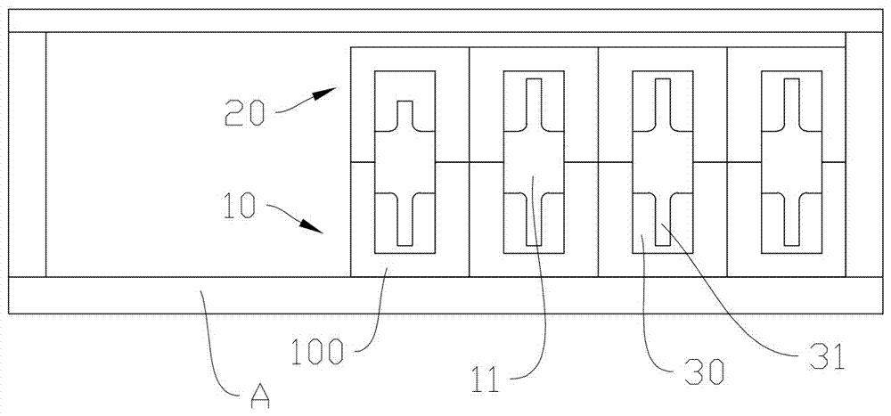
[0032] Embodiment 2: as Figure 3-4 As shown, a new type of busbar frame is erected on the busbar bridge A of the power distribution cabinet. The new type of busbar frame includes a vertically joined bottom frame 10 and a top frame 20. The bottom frame 10 and the top frame 20 have the same structure and are arranged in a mirror image; The frame 10 and the top frame 20 are provided with at least one opening slot 11 corresponding to the position on the opposite joint surfaces. The opening slot 11 is provided with a vertically slidable clamping block 30. Card holes 31 with suitable widths.
[0033] Two vertical groove walls of the opening slot 11 are provided with sliding grooves 111 , and the clamping block 30 is provided with a protrusion 32 which is slidably matched with the sliding grooves 111 .
[0034] The bottom frame 10 is formed by inserting a plurality of independent bottom frame modules 100 with open slots 11 , and the top frame 20 is formed by inserting and assemblin...
PUM
 Abstract
Description
Claims
Application Information
 - R&D
- Intellectual Property
- Life Sciences
- Materials
- Tech Scout
- Unparalleled Data Quality
- Higher Quality Content
- 60% Fewer Hallucinations
Browse by: Latest US Patents, China's latest patents, Technical Efficacy Thesaurus, Application Domain, Technology Topic, Popular Technical Reports.
© 2025 PatSnap. All rights reserved.Legal|Privacy policy|Modern Slavery Act Transparency Statement|Sitemap|About US| Contact US: help@patsnap.com


