Wring device, electrical box and air conditioner
A wiring device and electrical box technology, applied in the direction of electrical components, etc., can solve the problems of low wiring efficiency and inconvenience, and achieve the effect of convenient wiring, simple wiring operation, and improved wiring efficiency
- Summary
- Abstract
- Description
- Claims
- Application Information
AI Technical Summary
Problems solved by technology
Method used
Image
Examples
Embodiment 1
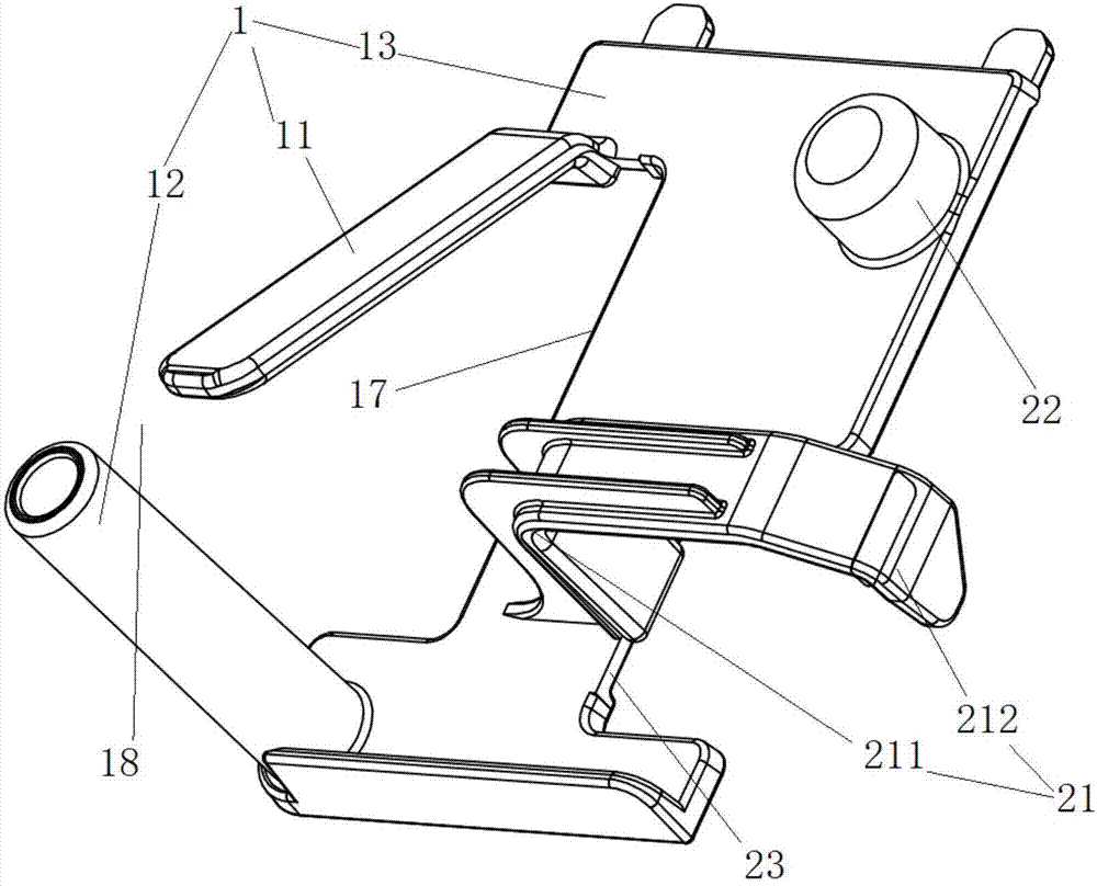
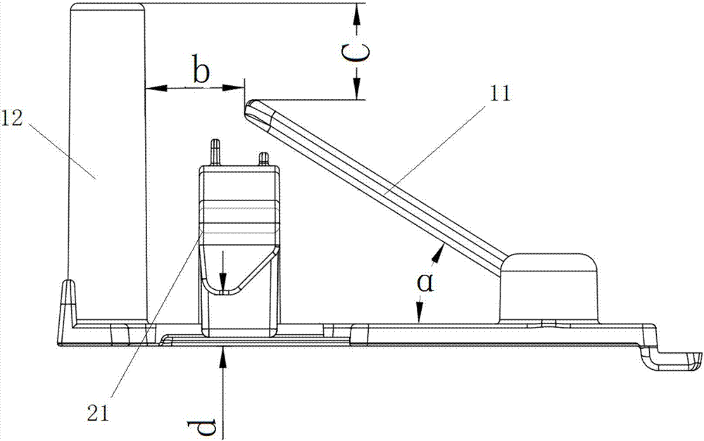
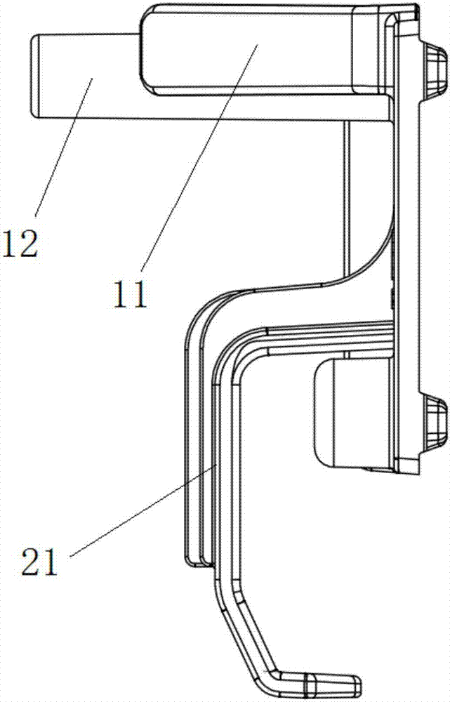
[0060] This embodiment provides a wiring device, such as Figure 1 to Figure 11 As shown, the wire routing device in this embodiment includes a wire passing limiting structure 1 and a wire winding structure 21 . Wherein, the wire-passing limiting structure 1 is used to lead in and out the wire body 5 and limit the wire body 5 . The wire winding structure 21 is located below the wire passing limiting structure 1 and is used to make the wire body 5 bypass. Wherein, after the wire body 5 is introduced into the wire routing device through the wire passing limiting structure 1, it winds around the wire winding structure 21 to form a water return bend.
[0061] The wire routing device provided in this embodiment can complete the wire routing operation only by introducing the wire body through the wire passing limiting structure 1, bypassing the wire winding structure 21, and then leading out from the wire passing limiting structure 1 through the above-mentioned settings. , compare...
Embodiment 2
[0065] Preferably, this embodiment provides a wiring device, compared with the previous embodiment, such as Figure 1 to Figure 11 As shown, the present embodiment further designs the limit structure 1 for crossing the line as follows:
[0066] The wire passing limiting structure 1 includes a bottom plate 13 , a first stopper and a second stopper. Wherein, the first stopper is arranged on the bottom plate 13 , and the second stopper is arranged on the bottom plate 13 . The first stopper, the second stopper and the bottom plate 13 encircle a limiting cavity, and the wire body 5 entering the limiting cavity is stopped on the first stopper, and the outgoing line end is stopped on the second stopper. on the stop.
[0067] Preferably, the first stopper is a limiting piece 11 ; the second stopper is a stop post 12 . The following content of this embodiment and the following embodiments mainly use the limiting sheet 11 as the first stopper and the stop post 12 as the second stoppe...
Embodiment 3
[0076] Preferably, this embodiment provides a wiring device, compared with the above embodiments, such as Figure 1 to Figure 11 As shown, the wire winding structure 21 in this embodiment is arranged on the bottom plate 13 for winding the wire body. Wherein, the wire body 5 enters from the side of the limit plate 11 of the wire-passing limit structure 1, and adapts to the operation habit of the human body, leads the wire body 5 to one side of the winding structure 21, and bypasses the winding structure 21, Lead out from the other side of the wire winding structure 21, and finally lead out the wire routing device from the side of the stop post 12 of the wire passing limiting structure 1 to complete the installation. The entire installation process can be completed with one hand, and the operation is simple.
[0077] Preferably, the winding structure 21 is made of elastic material. The elastic material makes the wire body have a certain tension at the winding structure 21 afte...
PUM
 Abstract
Description
Claims
Application Information
 - R&D
- Intellectual Property
- Life Sciences
- Materials
- Tech Scout
- Unparalleled Data Quality
- Higher Quality Content
- 60% Fewer Hallucinations
Browse by: Latest US Patents, China's latest patents, Technical Efficacy Thesaurus, Application Domain, Technology Topic, Popular Technical Reports.
© 2025 PatSnap. All rights reserved.Legal|Privacy policy|Modern Slavery Act Transparency Statement|Sitemap|About US| Contact US: help@patsnap.com


