Al technical title is built by PatSnap Al team. It summarizes the technical point description of the patent document.
A pin insertion device and automatic technology, applied in metal processing equipment, metal processing, manufacturing tools, etc., can solve the problems of high repetition rate, easy hand damage, easy brain fatigue, etc., and achieve good stability.
Pending Publication Date: 2017-12-12
QINGDAO UNIV OF SCI & TECH
View PDF5 Cites 5 Cited by
Summary
Abstract
Description
Claims
Application Information
AI Technical Summary
This helps you quickly interpret patents by identifying the three key elements:
Problems solved by technology
Method used
Benefits of technology
Problems solved by technology
[0002] Pin insertion equipment is a kind of equipment with relatively specific functions. Relying on the structural characteristics of its design, it can conveniently and quickly realize the functions of pin insertion and unloading, and it is easy to realize automatic operation. It can effectively solve the manual or semi-automatic pin insertion equipment in the factory. The repetition rate Disadvantages of high efficiency, low efficiency, easy fatigue of the brain, and easy damage to the hands
Method used
Image
Click on the blue label to locate the original text in one second.
Reading with bidirectional positioning of images and text.
Examples
Embodiment Construction
[0019] The technical solutions of the present invention will be further described below in conjunction with the accompanying drawings and through specific implementation methods.
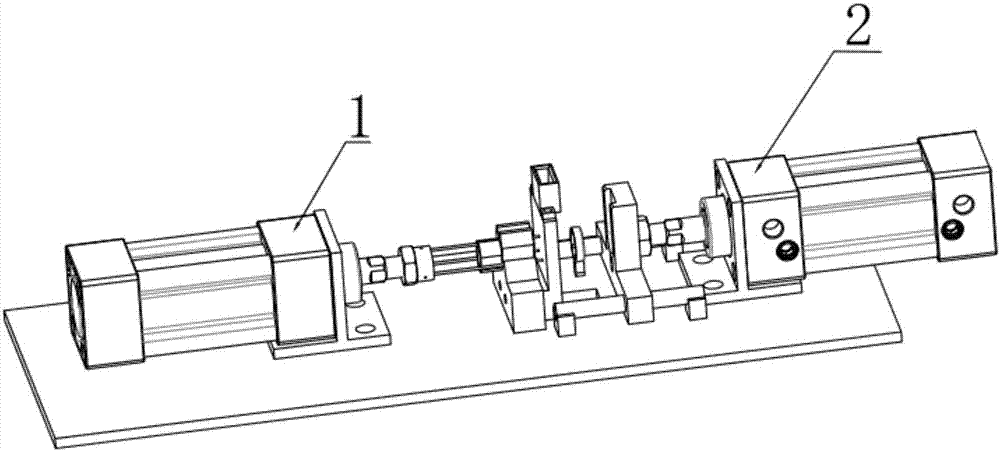
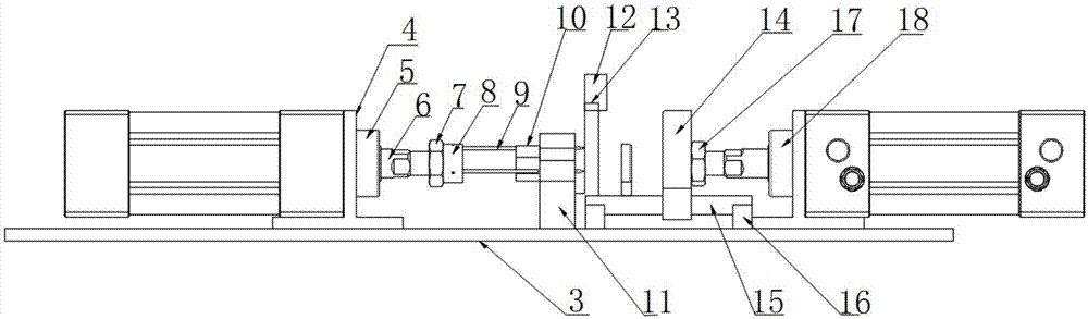
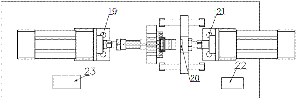
[0020] Such as figure 1 , 2 , 3, an automatic pin insertion device, including a pin insertion device 1, a discharge device 2, a base 3, a control system module 22, and a distribution box 23. The pin insertion device 1 includes: a fixed plate 4, a pin cylinder 5, a telescopic shaft 6, a clamping nut 7, a ferrule 8, a thimble rod 9, a push rod 10, a bracket 11, and a pin cylinder fixing plate hole 19; The fixed plate 4 is a 10mm thick T-shaped steel plate, which is integrally cut from structural steel; the pin cylinder 5 is fixed on the fixed plate 4, and the tail of the pin cylinder is in contact with the base 3; The telescopic shaft 6 is fixed on the pin cylinder 5; the clamping nut 7 is in contact with the side of the telescopic shaft 6, and the clamping nut 7 tightly withstands the ferrule 8; th...
PUM
Abstract
The invention discloses automatic needle insertion equipment. The automatic needle insertion equipment comprises a needle insertion device, an unloading device, a control system module and a base, wherein the needle insertion device, the unloading device, the control system module and a power distribution box are all fixed to the base; the needle insertion device comprises a fixing plate, a needle insertion cylinder, a telescopic shaft, a clamping nut, a ferrule, a needle ejection round rod, an ejection rod, a support and needle insertion cylinder fixing plate holes; the unloading device comprises a part base, a support movement guide rod, a fixing block, a jacking nut, an unloading cylinder, unloading cylinder fixing plate holes, a feeding pipeline, a clamping block and a workpiece clamping groove; and the control system module is composed of a pneumatic control module and a circuit control module, and takes a Mitsubishi Q-series PLC as a control core. The automatic needle insertion equipment disclosed by the invention is capable of realizing long-time continuous working, simple and convenient, and capable of easily realizing batch needle insertion, and solves the problems of high manual needle insertion repetition rate, low efficiency, and high possibility of brain fatigue and hand injury in a factory.
Description
technical field [0001] The invention relates to a needle insertion device, in particular to an automatic needle insertion device adopting pneumatic control and circuit control. Background technique [0002] Pin insertion equipment is a kind of equipment with relatively specific functions. Relying on the structural characteristics of its design, it can conveniently and quickly realize the functions of pin insertion and unloading, and it is easy to realize automatic operation. It can effectively solve the manual or semi-automatic pin insertion equipment in the factory. The repetition rate High efficiency, low efficiency, easy fatigue of the brain, and easy damage to the hands. At this stage, semi-automatic products are still the main products. Therefore, automatic pin insertion equipment has great potential in the market. Contents of the invention [0003] The object of the present invention is to provide an automatic pin insertion device to realize the automatic pin insert...
Claims
Application Information
Patent Timeline
Application Date:The date an application was filed.
Publication Date:The date a patent or application was officially published.
First Publication Date:The earliest publication date of a patent with the same application number.
Issue Date:Publication date of the patent grant document.
PCT Entry Date:The Entry date of PCT National Phase.
Estimated Expiry Date:The statutory expiry date of a patent right according to the Patent Law, and it is the longest term of protection that the patent right can achieve without the termination of the patent right due to other reasons(Term extension factor has been taken into account ).
Invalid Date:Actual expiry date is based on effective date or publication date of legal transaction data of invalid patent.