
Automatic snap spring assembling device

An automatic assembly device and circlip technology, which is applied in the direction of metal processing, metal processing equipment, manufacturing tools, etc., can solve the problems of difficult positioning of circlips, low work efficiency, complex structure, etc., to ensure accuracy and accuracy, reduce Labor cost, the effect of improving work efficiency

Active Publication Date: 2017-12-12
WUHAN LIANHANG ELECTROMECHANICAL
View PDF7 Cites 19 Cited by
  • Summary
  • Abstract
  • Description
  • Claims
  • Application Information

AI Technical Summary

Problems solved by technology

[0004] The object of the present invention is to provide an automatic circlip assembly device, which is used to solve the problems that the equipment or device for assembling the circlip into the inner hole has a complex structure, and the circlip is not easy to locate during the assembly process, and the work efficiency is low.

Method used


Image

  • Automatic snap spring assembling device
  • Automatic snap spring assembling device
  • Automatic snap spring assembling device

Examples


Embodiment Construction

[0066] The technical solutions of the present invention will be further described below in conjunction with the accompanying drawings and through specific implementation methods.

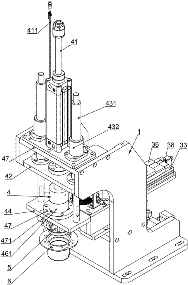
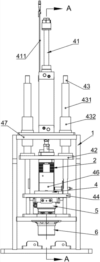
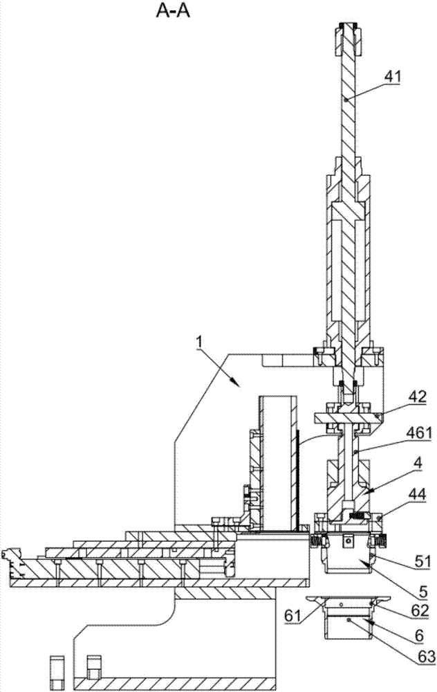
[0067] Such as Figure 1-4 As shown, the present embodiment provides an automatic assembly device for circlips, including a frame 1 and a storage unit 2, which is arranged on the frame 1 and used for stacking circlips 21; Figure 5 and Figure 6 As shown, the conveying unit 3 includes a conveying channel 31 arranged on the frame 1, a conveying thin plate 32, and a circlip conveying cylinder 33 that pushes the conveying thin plate 32 to reciprocate in the conveying channel 31; Directly below, the circlip 21 can fall into the conveying channel 31 from the storage unit 2, and is pushed away from the conveying channel 31 by the conveying thin plate 32 to directly above the circlip slot;

[0068] Such as Figure 1-4 As shown, the pressing unit 4 is arranged on the frame 1, and the circlip 21 located d...


PUM


Abstract

The invention relates to the technical field of snap spring assembling, and discloses an automatic snap spring assembling device. The automatic snap spring assembling device comprises a rack and further comprises a storage unit arranged on the rack and used for stacking snap springs, a conveying unit, a pressing unit and a control unit. The conveying unit comprises a conveying channel arranged on the rack, a conveying thin plate and a snap spring conveying air cylinder pushing the conveying thin plate to reciprocate on the conveying channel. The conveying channel is located under the storage unit, and the snap springs can fall into the conveying channel through the storage unit and are pushed by the conveying thin plate to disengage from the conveying channel to the position over a snap spring groove. The pressing unit is arranged on the rack and presses the snap spring over the snap spring groove into the snap spring groove. The storage unit, the conveying unit and the pressing unit are electrically connected to the control unit. The problems that existing equipment or a device for assembling snap springs into inner holes, the structure is complex, the snap springs are not prone to being positioned in the assembling process, and the work efficiency is low are solved.

Description

technical field [0001] The invention relates to the technical field of circlip assembly, in particular to an automatic assembling device for circlips. Background technique [0002] Generally, the assembly of the circlip is done manually using some special equipment. When the circlip groove of the circlip assembly is located at a deep position in the inner hole, the difficulty of manual assembly with the circlip pliers increases, the efficiency is low, and manual assembly exists. Risk of missing circlips, missing circlips may cause serious accidents. [0003] The material feeding and conveying mechanism of the inner hole circlip automatic assembly device in the prior art performs material feeding by means of air blowing and vibration. Specifically, the circlip feeding plate is provided with a circlip channel for conveying the circlip, one side of the circlip feeding plate is connected with a feeding conveying mechanism, and the feeding conveying mechanism is provided with a ...

Claims


Application Information

Patent Timeline
Patent Type & Authority Applications(China)
IPC IPC(8): B23P19/027B23P19/00
CPCB23P19/001B23P19/027Y02P70/50
Inventor 沈国双裴明丰张晖魏杰汪伟
Owner WUHAN LIANHANG ELECTROMECHANICAL
Learn More