electric assist bike rack

A bicycle frame and electric power assist technology, applied in vehicle parts, vehicle gearbox, rider drive, etc., can solve the problems of insufficient comfort and large force of human-driven vehicles, so as to improve riding comfort and compact structure. Moreover, the effect of high transmission efficiency

Inactive Publication Date: 2019-10-01
天津基泰科技有限公司
View PDF5 Cites 0 Cited by
  • Summary
  • Abstract
  • Description
  • Claims
  • Application Information

AI Technical Summary

Problems solved by technology

[0004] There are many related documents about electric bicycles, such as a kind of electric bicycle (publication number CN1237520A) recorded in Chinese patent literature, although this electric bicycle can make the speed superposition of motor drive and human-driven vehicle; Large force required and insufficient comfort

Method used


Image

  • electric assist bike rack
  • electric assist bike rack
  • electric assist bike rack

Examples


Embodiment 1

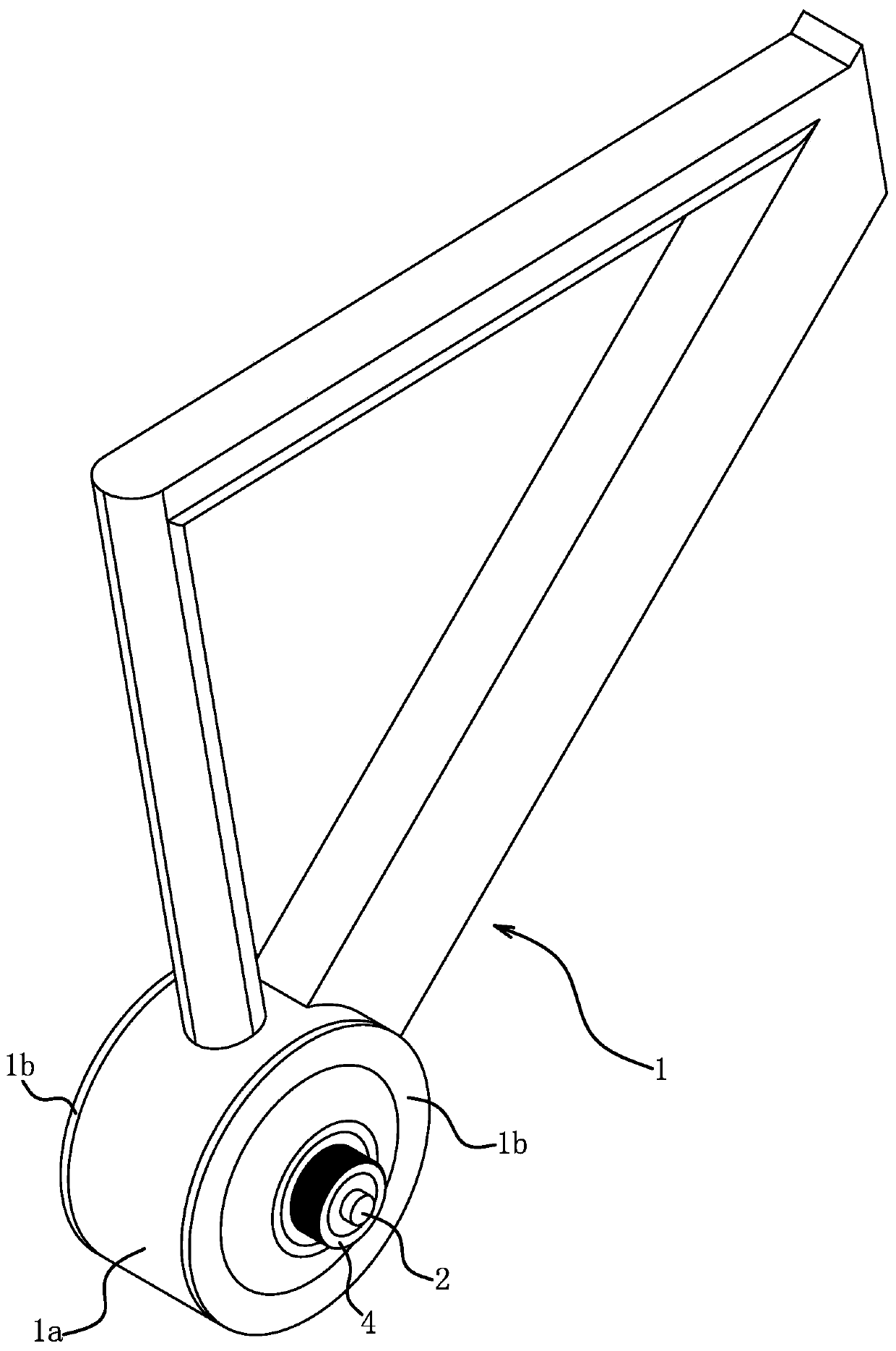
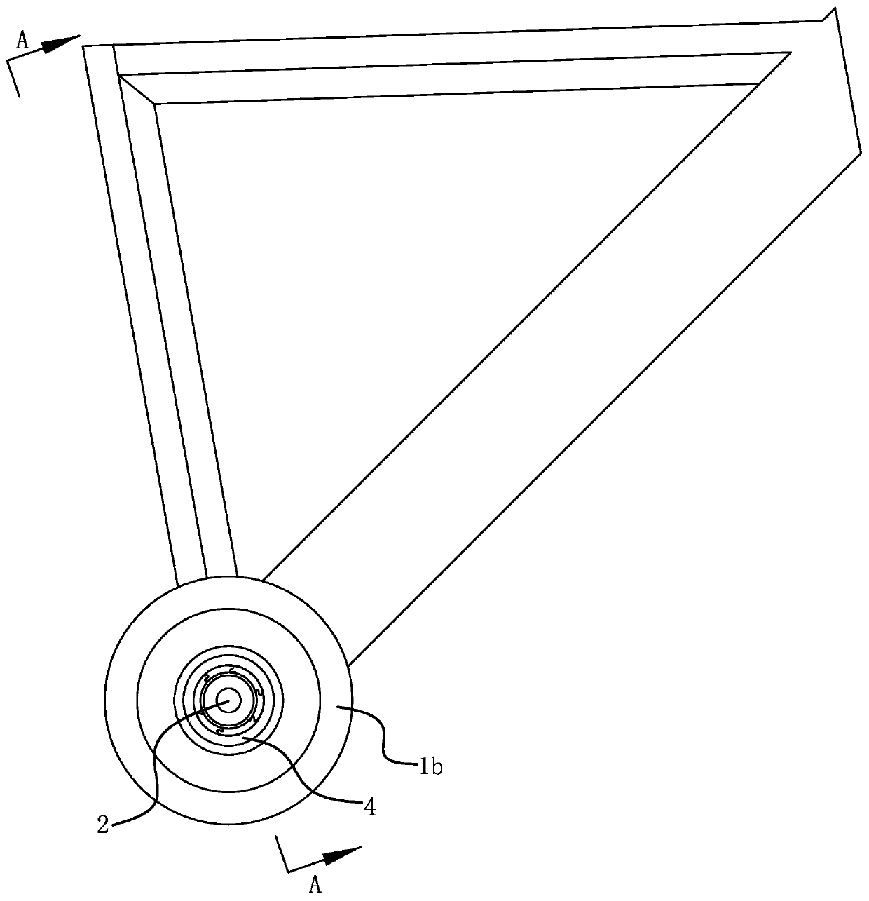
[0018] Such as Figure 1 to Figure 3 As shown, the electric power-assisted bicycle frame includes a vehicle frame 1, a pedal shaft 2, a planetary gear assembly, an output shaft 4 and a motor 3.

[0019] Such as figure 1 As shown, the vehicle frame 1 is triangular in shape, and the bottom of the vehicle frame 1 has a circular tube-shaped installation part 1a, and both ends of the installation part 1a are fixedly connected with end covers 1b by bolts. According to actual conditions, the vehicle frame 1 can also adopt other shapes.

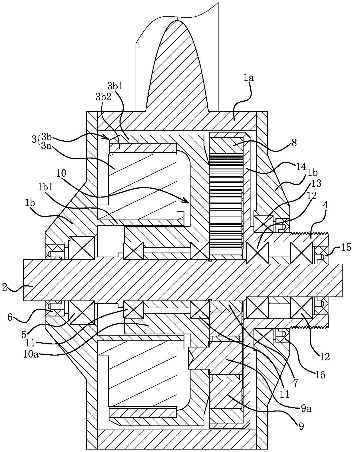
[0020] Such as image 3 As shown, the pedal shaft 2 is passed through the installation part 1a, and one end of the pedal shaft 2 passes through the end cover 1b located on one side of the installation part 1a, and the other end of the pedal shaft 2 passes through the end cover located on the other side of the installation part 1a. The cover 1b is threaded out. The pedal shaft 2 is connected to the end cover 1b located on the side of the installat...

Embodiment 2

[0032] As shown in 4, the electric power-assisted bicycle frame includes a vehicle frame 1, a pedal shaft 2, a planetary gear assembly and a motor 3.

[0033] The bottom of the vehicle frame 1 has a circular tube-shaped mounting portion 1a, and both ends of the mounting portion 1a are fixedly connected with end covers 1b by bolts. The pedal shaft 2 is passed through the installation part 1a, and one end of the pedal shaft 2 passes through the end cover 1b on one side of the installation part 1a, and the other end of the pedal shaft 2 passes through the end cover 1b on the other side of the installation part 1a. out. Both the pedal shaft 2 and the end cover 1b are connected through the fifth bearing 17, and a fourth sealing ring 18 is also provided between the pedal shaft 2 and the end cover 1b.

[0034] The planetary gear assembly and the motor 3 are located in the mounting portion 1a. Both the motor 3 and the planetary gear assembly are sleeved on the pedal shaft 2 . The m...


PUM


Abstract

The invention provides an electric-powered bicycle frame, and belongs to the technical field of bicycles. The electric-powered bicycle frame solves the problem that existing electric bicycles require relatively strong force when driven by manpower. The electric-powered bicycle frame comprises a frame and a pedal shaft; a planetary gear assembly is located between an output shaft and a motor; a sun gear is fixedly connected with the pedal shaft, a planet carrier is rotatably connected with the frame or the pedal shaft, and an outer gear ring is fixedly connected with the output shaft; and a stator of the motor is fixedly connected with the frame, and an rotor of the motor is fixedly connected with the planet carrier. According to the electric-powered bicycle frame, manpower and motor driving force are input to the sun gear and the planetary frame, and the power is output through the outer gear ring. When both the manpower and the motor driving force are input together, the direction of the force of pedaling the pedal is the same as the direction of the output force of the motor, thus the problem of increasing the force required when the bicycle is pedaled to drive the bicycle is solved and the riding comfort is improved.

Description

technical field [0001] The invention belongs to the technical field of bicycles, and relates to a bicycle frame, in particular to an electric power-assisted bicycle frame. Background technique [0002] A bicycle is usually a small land vehicle with two wheels. After a person rides on the car, it is powered by pedals, which is a green and environmentally friendly means of transportation. [0003] An electric bicycle refers to a mechatronic personal vehicle that uses a battery as an auxiliary energy source on the basis of an ordinary bicycle, and is equipped with operating components such as a motor, a controller, a battery, a handlebar, and a display instrument system. [0004] There are many related documents about electric bicycles, such as a kind of electric bicycle (publication number CN1237520A) recorded in the Chinese patent literature, although this electric bicycle can make the speed superposition of motor drive and human-driven vehicle; The problem of large force a...

Claims


Application Information

Patent Timeline
Patent Type & Authority Patents(China)
IPC IPC(8): B62M6/40B62M23/02
Inventor 蒋先正
Owner 天津基泰科技有限公司
Why Eureka
Try Eureka