Self-floating towing marine wind power floating foundation and construction method thereof

An offshore wind power and self-floating towage technology, which is applied in wind power generation, floating buildings, ships, etc., can solve the problems of high tensile force and shorten the service life of ropes, so as to reduce the impact force, increase the stability, and improve the stability. sexual effect

Active Publication Date: 2021-11-16
SHANGHAI MUNICIPAL ELECTRIC POWER CO
View PDF8 Cites 2 Cited by
  • Summary
  • Abstract
  • Description
  • Claims
  • Application Information

AI Technical Summary

Problems solved by technology

[0004] In view of this, in order to solve the problem that the ropes on the side of the anchoring system in the floating foundation of offshore wind turbines will bear a large pulling force when the floating foundation is impacted, which will reduce the service life of the ropes, the present invention provides a self-floating tow Nautical offshore wind power floating foundation and its construction method

Method used


Image

  • Self-floating towing marine wind power floating foundation and construction method thereof
  • Self-floating towing marine wind power floating foundation and construction method thereof
  • Self-floating towing marine wind power floating foundation and construction method thereof

Examples


Embodiment 1

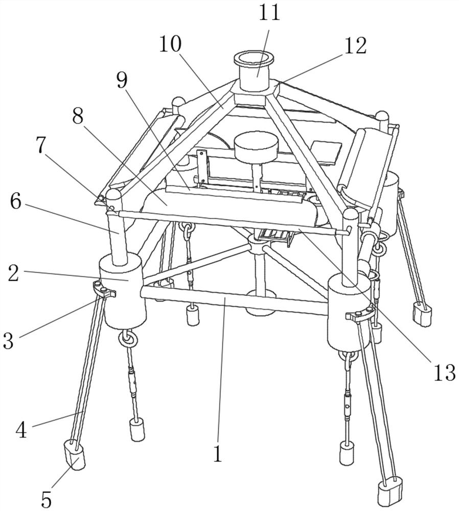
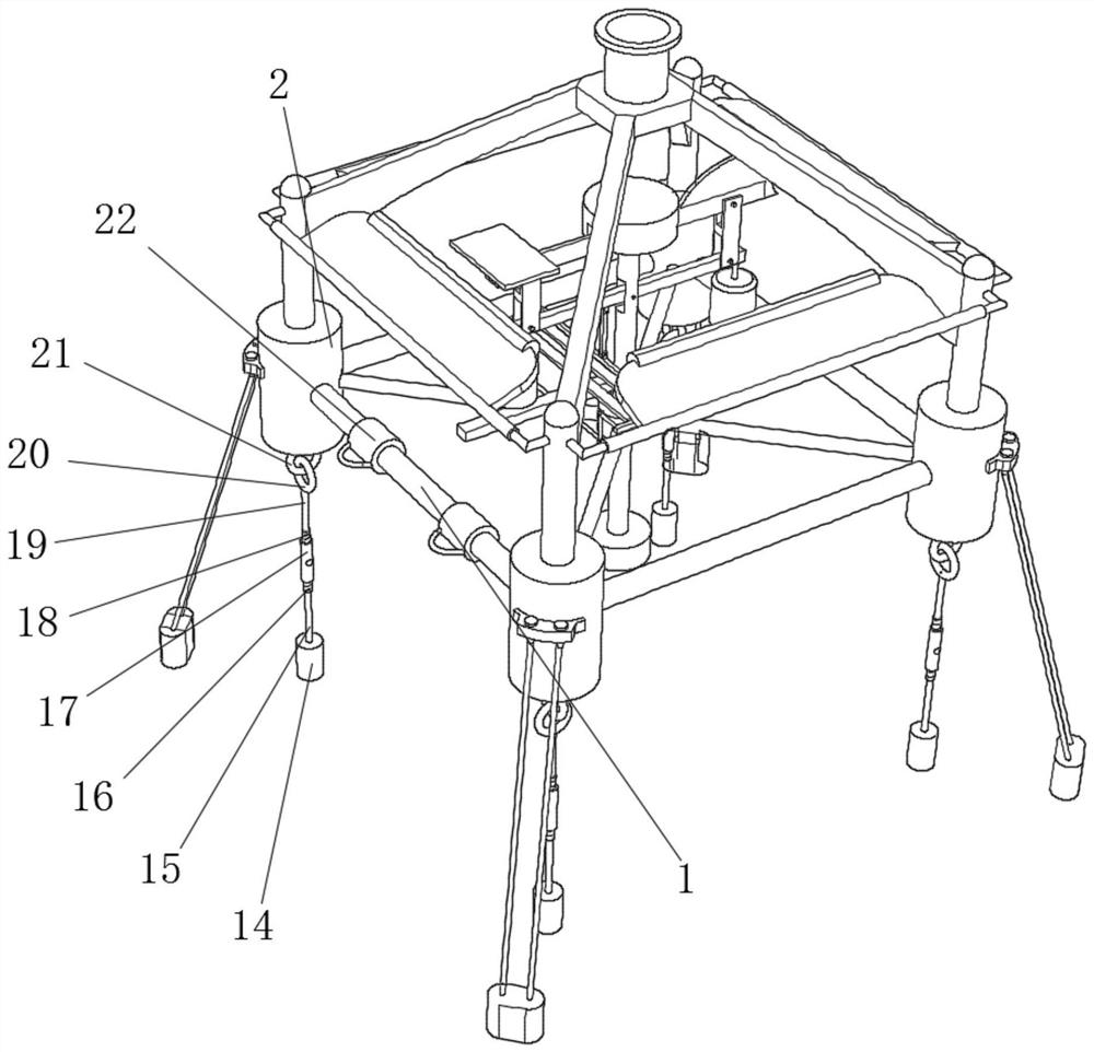
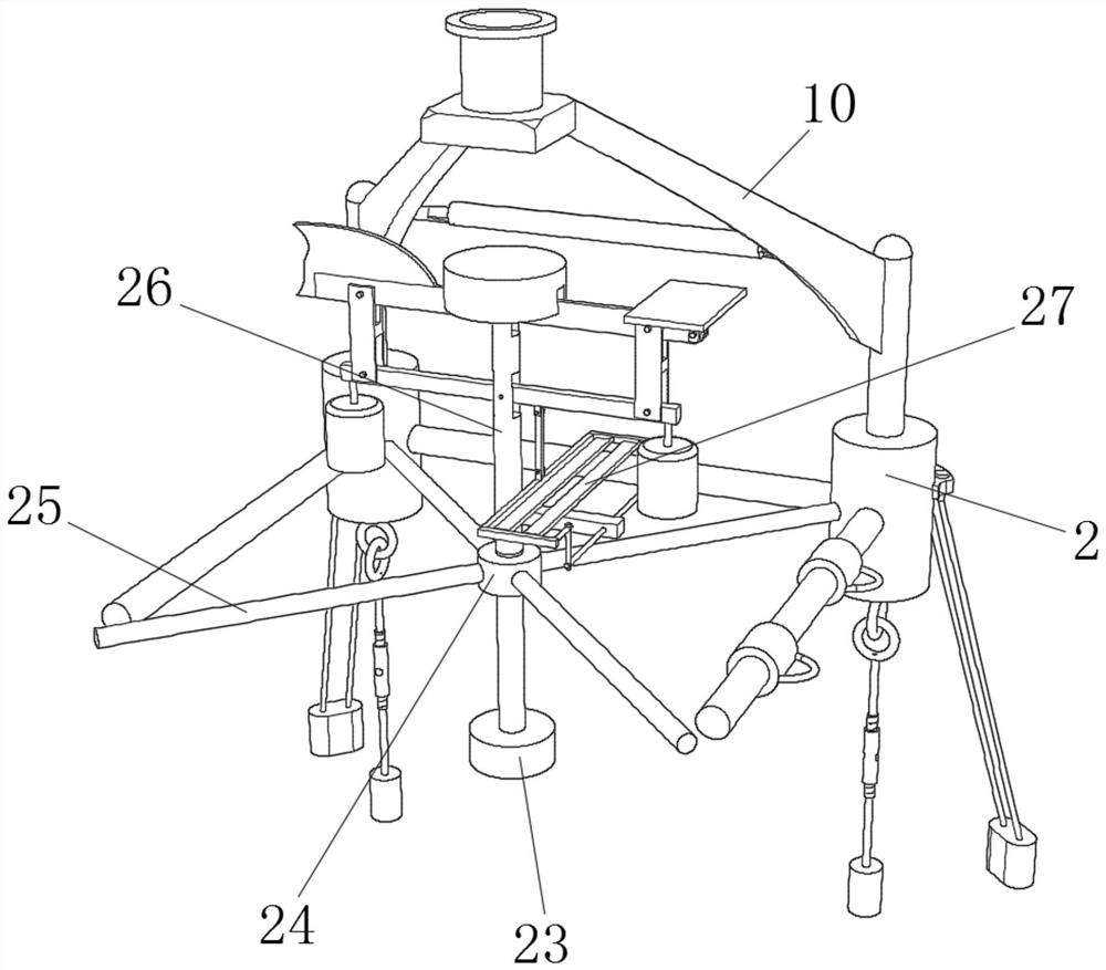
[0038] Such as Figure 1-Figure 6 As shown, a self-floating towed offshore wind power floating foundation includes a plurality of main buoys 2, and connecting rods 1 are fixed between the main buoys 2 through bolts. The main buoys 2 provide the main buoyancy for the whole device, which is convenient for other equipment. Install, one side of main buoy 2 is all fixed with connecting rod 25 by bolt, is fixed with guide ring 24 by bolt between connecting rod 25, is provided with balance mechanism 26 in guide ring 24.

[0039] In the present invention, the balance mechanism 26 includes an insertion rod 28, which is slidably connected in the guide ring 24, and the guide ring 24 plays a position-limiting role, and the insertion rod 28 can rotate and slide in the guide ring 24, and the insertion rod 28 The top of the top is fixed with a fixed buoy 33 by bolts, and one side of the insertion rod 28 is provided with two installation grooves 36, and the first fixed rod 30 and the second f...

Embodiment 2

[0042] refer to Figure 1-Figure 6 , the present invention provides a new technical solution, a self-floating towed offshore wind power floating foundation, including a plurality of main buoys 2, one side of the main buoys 2 is fixed with a fixed block 3 by bolts, and the bottom of the fixed block 3 The side rope 4 is fixed by bolts, and the bottom of the side rope 4 is fixed with the first fixing seat 5 by bolts, and the device is reinforced by the side rope 4 to improve the stability of the installation of the device. The connecting rods are fixed by bolts between the main buoys 2 1. The main buoy 2 provides the main buoyancy for the whole device, which is convenient for the installation of other equipment. One side of the main buoy 2 is fixed with a connecting rod 25 by bolts, and a guide ring 24 is fixed between the connecting rods 25 by bolts. The guide ring 24 Equipped with a balance mechanism 26;

[0043] In the present invention, the balance mechanism 26 comprises a p...


PUM


Abstract

The invention provides a self-floating towing marine wind power floating foundation, fixing blocks are fixed to one sides of main buoys through bolts, side ropes are fixed to the bottoms of the fixing blocks through bolts, first fixing bases are fixed to the bottoms of the side ropes through bolts, the device is reinforced through the side ropes, and the installation stability of the device is improved; connecting rods are fixed between the main buoys through bolts, the main buoys provide main buoyancy for the whole device, installation of other equipment is facilitated, connecting rods are fixed to one sides of the main buoys through bolts, guide rings are fixed between the connecting rods through bolts, and balance mechanisms are arranged in the guide rings. The problem that in an existing offshore wind turbine floating foundation, a rope on one side of an anchoring system can bear large pulling force when the floating foundation is impacted, and consequently the service life of the rope is shortened is solved.

Description

technical field [0001] The invention belongs to the technical field of offshore wind power foundations, and relates to a self-floating towed offshore wind power floating foundation and a construction method thereof. Background technique [0002] As we all know, as the water depth increases, the cost of fixed foundations such as pile-supported foundations will become higher and higher, especially when the water depth exceeds 50m, while the floating foundation uses an anchor system to anchor the floating structure to the seabed, and As a basic platform for installing wind turbines to generate electricity by sea wind, it is especially suitable for sea areas with a water depth of more than 50m. It has the advantages of low cost and convenient transportation. The floating foundation of offshore wind turbines is developed from the foundation of offshore oil production platforms. High development prospects. [0003] The installation position of the existing floating foundation for...

Claims


Application Information

Patent Timeline
Patent Type & Authority Applications(China)
IPC IPC(8): B63B35/44B63B75/00B63B77/10
CPCB63B35/44B63B75/00B63B77/10B63B2035/446Y02E10/727
Inventor 周盼高绪垚
Owner SHANGHAI MUNICIPAL ELECTRIC POWER CO
Why Eureka
Try Eureka