Three-degree-of-freedom large-stroke micro-positioning platform achieving driving force decoupling

A technology of micro-positioning platform and degree of freedom, which is applied to the parts of the instrument, the instrument, the shell, etc., can solve the problems of affecting the performance of the positioning platform, low response ability, and low carrying capacity, so as to improve the rotational stiffness and motion accuracy, improve Motion accuracy, effect of high natural frequency

Active Publication Date: 2017-12-12
TIANJIN UNIV
View PDF7 Cites 13 Cited by
  • Summary
  • Abstract
  • Description
  • Claims
  • Application Information

AI Technical Summary

Problems solved by technology

[0003] Traditional mechanisms are usually connected by kinematic pairs, which are composed of assembled assemblies, which have disadvantages such as friction, lubrication, and empty back characteristics.
Existing micro-positioning platforms widely use flexible hinge components, and use the resettable elastic deformation of the weak part of the rod to transmit motion, force and energy. It has many advantages such as no mechanical friction, no gap, no lubrication, stable movement, and high sensitivity. Accurate angular deformation in a small range, combined with the widely used parallel structure at the same time, overcomes the shortcomings of the traditional series configuration,

Method used


Image

  • Three-degree-of-freedom large-stroke micro-positioning platform achieving driving force decoupling
  • Three-degree-of-freedom large-stroke micro-positioning platform achieving driving force decoupling
  • Three-degree-of-freedom large-stroke micro-positioning platform achieving driving force decoupling

Examples


Example Embodiment

[0020] The present invention will be further explained with the accompanying drawings. The embodiments of the present invention are to better enable those skilled in the art to better understand the present invention, and do not limit the present invention in any way.
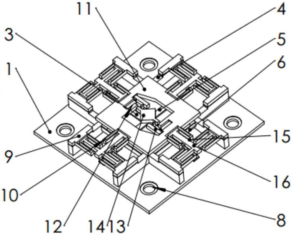
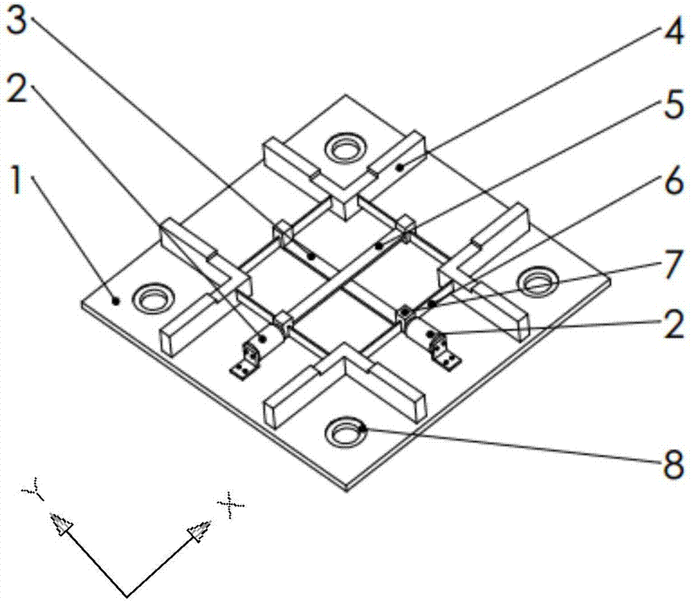
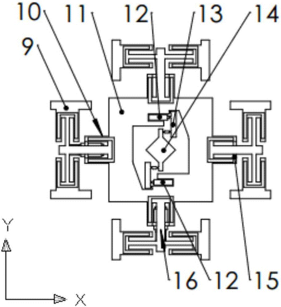
[0021] Such as Figure 1 to Figure 3 , A three-degree-of-freedom large-stroke micro-positioning platform with driving force decoupling, comprising a micro-movement platform base, which sequentially includes a bottom plate 1, a middle part, and a top part from bottom to top, and the bottom plate 1 is provided There are positioning holes 8, and bosses 4 are arranged on the four top corners of the bottom plate 1 to support the top part; a parallel plate guide mechanism 6 is connected between two adjacent bosses 4, a parallel plate guide mechanism A central boss 7 is provided in the middle of the base plate 1. A voice coil motor driver 2 is arranged at the central boss 7 at one end in the X direction and the Y direct...


PUM


Abstract

The invention discloses a three-degree-of-freedom large-stroke micro-positioning platform achieving driving force decoupling. The three-degree-of-freedom large-stroke micro-positioning platform comprises a micro-moving platform base body which sequentially comprises a bottom plate, a middle part and a top layer part from bottom to top; two transferring beams are arranged in the center of the middle part, wherein the first transferring beam is used for connecting the middle part and flexible hinge deformation structures of two Y-direction ends of the top layer part, and the second transferring beam is used for connecting the middle part and flexible hinge deformation structures of two X-direction ends of the top layer part; the top layer part is sequentially provided with the flexible hinge deformation structures, a moving platform and an output platform from outside to inside, and the output platform is arranged in the center of the moving platform; and the two ends of the output platform are connected with piezo-ceramic actuators through lever amplifying mechanisms correspondingly. According to the three-degree-of-freedom large-stroke micro-positioning platform achieving driving force decoupling, the flexible beams are used for connecting two decoupled parts of the moving platform, and equal distribution and decoupling of the driving force are achieved; and through driving of two voice coil motors, high-precision and large-stroke movement of the moving platform in the X-Y plane is achieved.

Description

technical field [0001] The present invention relates to the technical field of micro-positioning platforms, in particular to a three-degree-of-freedom large-stroke micro-positioning platform with driving force decoupling, in particular to a three-degree-of-freedom large-stroke high-precision platform driven by a voice coil motor and piezoelectric ceramics , driving force decoupling flexible micro-positioning platform, used in microelectronics manufacturing, biomedical engineering, optical micro-assembly and ultra-precision processing and other fields. Background technique [0002] With the continuous development of fields such as microelectronics manufacturing, biomedical engineering, optical microassembly and ultra-precision machining, these fields also put forward higher requirements for micro-positioning platforms. The current micro-positioning platform technology has made great progress, but there is still a lot of room for improvement in terms of response speed, stabili...

Claims


Application Information

Patent Timeline
IPC IPC(8): G12B9/10G12B5/00
CPCG12B5/00G12B9/10
Inventor 霍至琛王福军梁存满田延岭张大卫
Owner TIANJIN UNIV
Why Eureka
Try Eureka