Centrifugal separator

a centrifugal separator and centrifugal technology, applied in centrifuges and other directions, can solve the problems of unfavorable separators with belt drives, unfavorable centrifugal separators, and possible relative motions of the rotor axis in the bearing plane, and achieve the effect of low cost and high power outpu

Inactive Publication Date: 2005-11-01
WESTFALIA SEPARATOR AG
View PDF35 Cites 27 Cited by
  • Summary
  • Abstract
  • Description
  • Claims
  • Application Information

AI Technical Summary

Benefits of technology

[0008]An advantage of this configuration is that the motor is decoupled from the rotational motion of the spindle and drum. The flexible elastic coupling element between spindle and drum can compensate angular displacement and minor radial displacement between the axes so that no strong flex load of the motor shaft and motor rotor bearing arises. Thus, low-cost use of standard motors is possible. The mass of the suspended system and of the motor mass is reduced by the fixed mounting of the motor to the centrifuge frame, and it is possible to use heavy motors with high power output. Major losses of power output that might lead to warming of the frame no longer occur in the drive train because of the direct coupling of the motor to the spindle, so that the centrifuge based on the invention is basically suited for use in an explosive environment.
[0009]Suspension of the rotating system in a bearing pot that is connected via elastic support elements to the frame leads to the fact that angular displacement arises only between the bearing pot and the frame, while the angular displacement between the inner ring and outer ring of a particular bearing is greatly reduced. Thus, standard roller bearings may be used.

Problems solved by technology

However, the rotor may also deviate radially because of the elasticity of the element so that, in addition to the circular motion, unforeseeable relative motions of the rotor axis in the bearing plane are possible.
Slippage in the drive belt leads to losses in drive output.
This known separator with a belt drive is therefore undesirable in many explosive environments.
Also, the transferable drive output is limited.
A disadvantage of this configuration is that the lower bearing must also function as a revolving joint, thus requiring special implementation of roller bearings.
The size and weight of the motor, and thereby also the motor output, is thus limited by the motor suspended with the spindle and drum.
The known design for heavy motors with high output is not suitable because of the inertial forces and bearing loads that must be handled.

Method used


Image

  • Centrifugal separator
  • Centrifugal separator
  • Centrifugal separator

Examples


Embodiment Construction

[0016]The preferred embodiments of the present invention will now be described with reference to FIGS. 1–3b of the drawings. Identical elements in the two figures are designated with the same reference numerals.

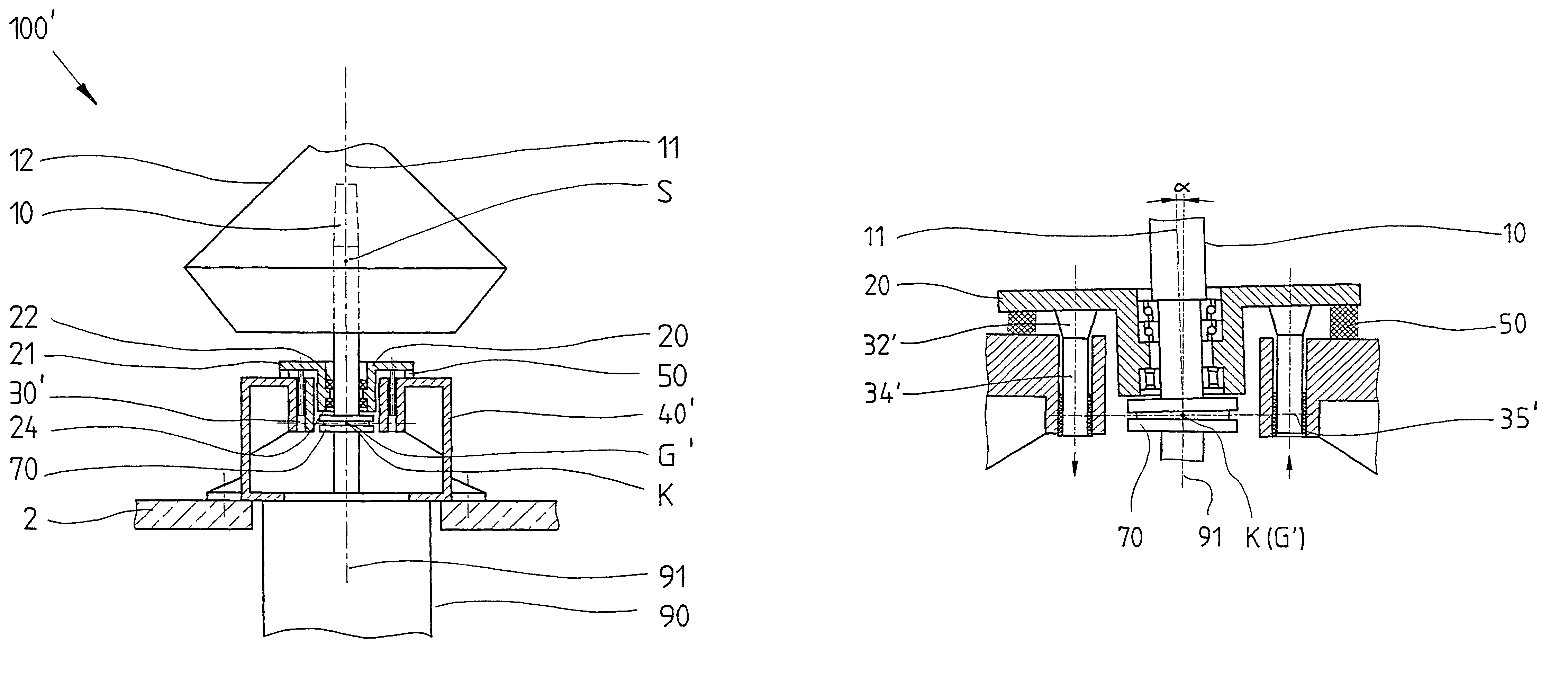
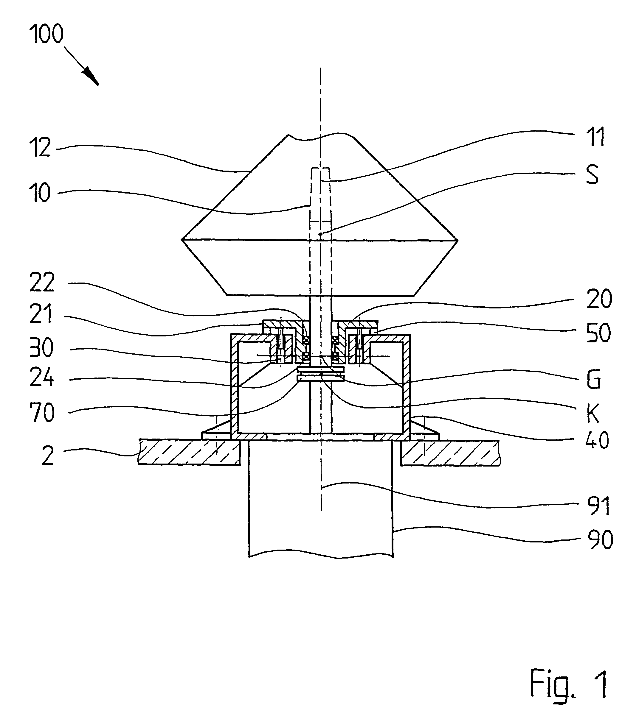
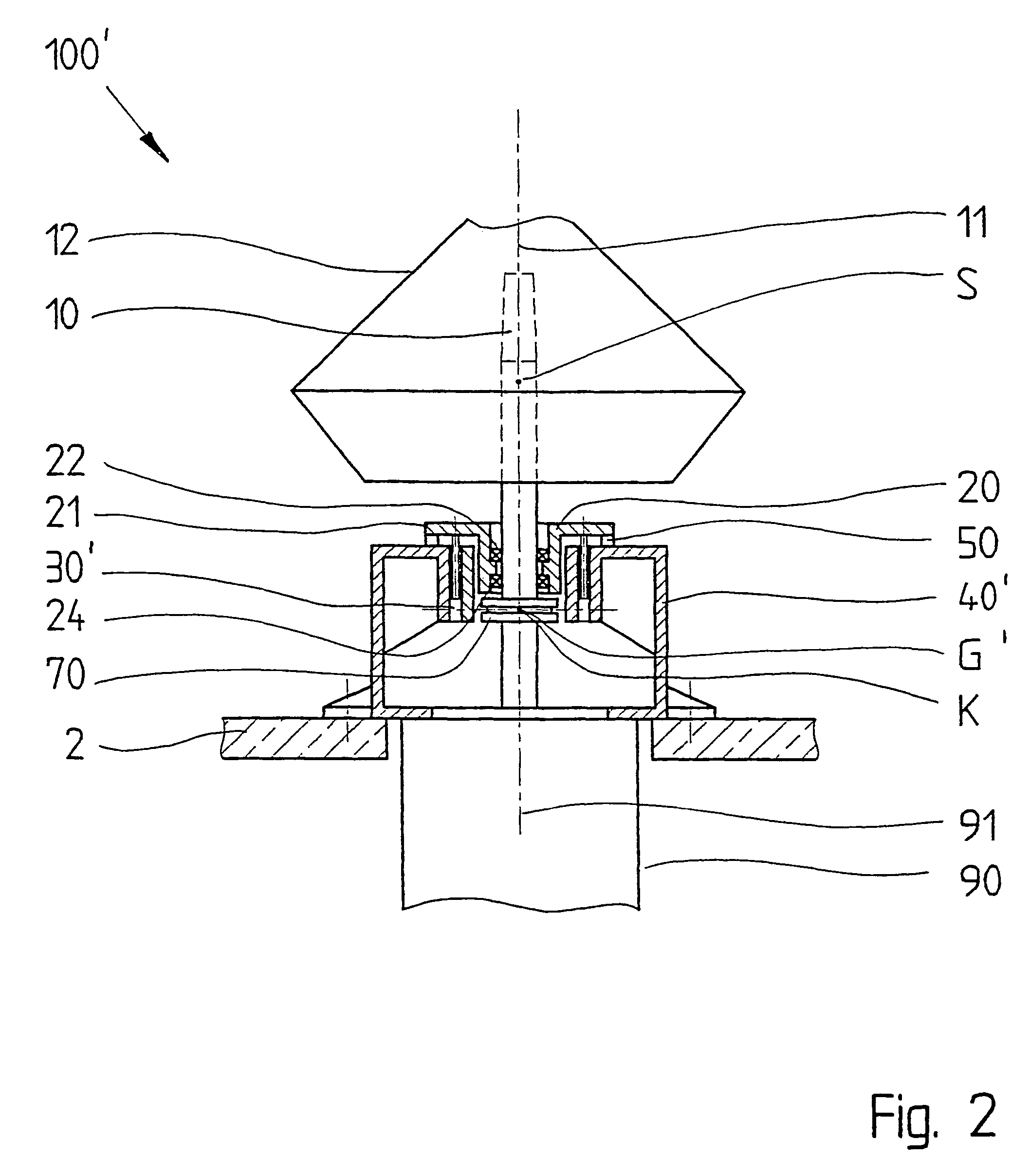
[0017]FIG. 1 shows a centrifugal separator 100 in a complete cutaway view. A motor 90 is secured to the underside of a centrifuge frame bolted to a base 2. A bearing pot 20 is installed into the upper side of the frame 40 that is supported by elastic support elements 50 and held by guide pins 30. A vertically-oriented spindle on which a drum 12 is placed is mounted so that it may rotate.

[0018]The spindle 10 is connected to the motor 90 via a flexible elastic coupling element 70. A slotted clutch bearing shell and a feather key may be provided for torque transmission. The longitudinal axis 11 of the spindle 10 and the rotor axis 91 coincide when the centrifugal separator 10 is at rest.

[0019]The bearing pot 20 particularly includes a bearing pot collar 21, an upper bearing 22, ...


PUM


Abstract

The invention relates to a centrifugal separator (100) comprising a centrifugal frame (40), a rotatable, vertically arranged, drive spindle (100) provided with a drum (12), and a motor (90) having a vertical rotor axis (91). The spindle (10) is rotatably mounted in a bearing pot (20) and is mounted in a manner that permits it to three-dimensionally move about a pivot (G) in relation to the centrifugal frame (40). The housing of the motor (90) is rigidly fixed to the centrifugal frame (40), with the rotor axis (91) of the motor (90) aligned with the longitudinal axis (11) of the drive spindle (10) when at rest. The motor rotor is connected to the spindle (10) at a coupling point (K) via a flexible coupling element (70). The spindle (10) is mounted in the bearing pot (20) at at least two interspaced bearing points (22, 24) by means of antifriction bearings. The bearing pot (20) is joined to the centrifugal frame (40) via elastic bearing elements (50).

Description

BACKGROUND OF THE INVENTION[0001]The invention relates to a centrifugal separator with a centrifuge frame, a rotatable, vertically-positioned spindle with a drum mounted on it, and a motor whose rotational axis is positioned vertically, whereby the spindle is supported in a bearing pot so that it may rotate and may be suspended from a pivot point connected to the frame that may move through three dimensions.[0002]Such a centrifugal separator is known from U.S. Pat. No. 2,827,229. In this, the rotor and the frame are connected with each other via an elastic element that allows oscillation of the rotor. However, the rotor may also deviate radially because of the elasticity of the element so that, in addition to the circular motion, unforeseeable relative motions of the rotor axis in the bearing plane are possible.[0003]Such a centrifugal separator is also known from The German Patent No. DE 31 25 832. In this, the crucial point of the suspended drive components coincides with the pivo...

Claims


Application Information

Patent Timeline
Patent Type & Authority Patents(United States)
IPC IPC(8): B04B9/12
CPCB04B9/12
Inventor MACKEL, WILFRIED
Owner WESTFALIA SEPARATOR AG
Why Eureka
Try Eureka