
A steel mesh component based on automatic spot welding technology

A steel mesh and automatic spot welding technology, which is applied to building components, structural elements, building reinforcements, etc., can solve the problems of reduced performance of reinforced concrete structures, lack of steel mesh components, and violation of economics and practicality, etc., to achieve space occupancy Low, easy to transport, reduce the effect of work difficulty

Active Publication Date: 2021-10-22
江苏若琪建筑产业有限公司
View PDF0 Cites 0 Cited by
  • Summary
  • Abstract
  • Description
  • Claims
  • Application Information

AI Technical Summary

Problems solved by technology

[0005] First of all, due to the different requirements for building use, the steel mesh pieces need to be made into corresponding sizes according to non-standard requirements, which is troublesome, and for some large-sized steel mesh pieces, it is not easy to transport and the transportation cost is high. Therefore, there is a lack of an easy-to-transport steel mesh member;
[0006] Secondly, due to the thickness limitation of the steel mesh, when pouring concrete, the thickness of the reinforced concrete obtained by pouring the concrete and the steel mesh is not enough, resulting in a decrease in the performance of the reinforced concrete structure, and to achieve the performance, it is often necessary to lay multiple layers of steel mesh , which increases the cost of use in a disguised form, which violates the purpose of economy and practicality. Therefore, there is a lack of an adjustable steel mesh member to match the actual concrete pouring thickness.

Method used


Image

  • A steel mesh component based on automatic spot welding technology
  • A steel mesh component based on automatic spot welding technology
  • A steel mesh component based on automatic spot welding technology

Examples


Embodiment 1

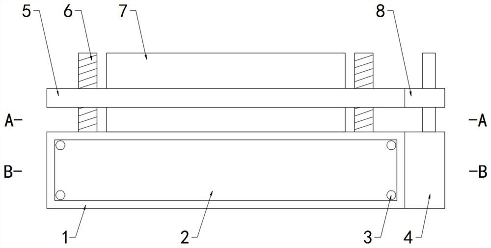
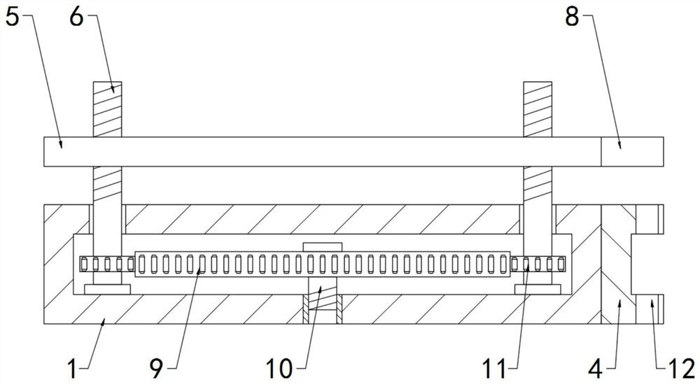
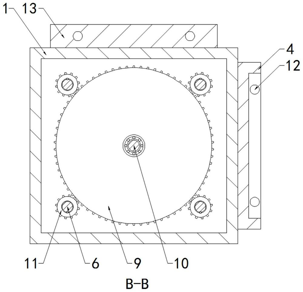
[0038] see Figure 1-5, a reinforcement mesh member based on automatic spot welding technology, including a base 1 and longitudinal reinforcement bars 17 and transverse reinforcement bars 18 distributed in a mesh shape, a plurality of longitudinal reinforcement bars 17 and transverse reinforcement bars 18 are welded at the intersection, and the longitudinal reinforcement bars 17 and A positioning frame 5 is welded on the outer side of the reinforcement mesh composed of transverse reinforcement bars 18, and corner reinforcing ribs 20 are welded between the surface walls on both sides of the positioning frame 5 to prevent the positioning frame from expanding and bursting after pouring concrete, and to improve the reinforcement mesh. The strength of the sheet, the obliquely-stayed rib 19 is welded between the two corner ribs 20 on the diagonal, and the two obliquely-stayed ribs 19 are welded at the intersection, the obliquely-stayed rib 19 and the corner rib 20 is symmetrically a...

Embodiment 2

[0041] The difference from Example 1 is that

[0042] see Figure 4 One side of the positioning frame 5 is fixedly connected with a connecting frame 8, and a rotating roller 15 is installed between the inner surface walls at both ends of the connecting frame 8, and a metal mesh 16 is wound around the outer side of the rotating roller 15, and the metal mesh 16 is drawn to cover the existing Concrete is poured above the steel mesh sheet, and concrete is poured twice on the metal mesh 16 to increase the pouring density of the concrete, further improve the structural performance of the reinforced concrete formed between the concrete and the steel mesh sheet, increase the structural stability, and transfer The roller 15 and the metal mesh 16 are installed on one side of the positioning frame 5, the space occupancy rate is low, and the transportation difficulty is not increased.

Embodiment 3

[0044] The difference from Example 1 is that

[0045] see Figure 4 with Figure 5 , the positioning frame 5 near the outer edge and the top of the connecting frame 8 are provided with a fixed through groove 14, and the corresponding position on the base 1 is provided with a fixed groove 21, and a unified stopper is inserted between the fixed through groove 14 and the fixed groove 21. Plate 7, when concrete is poured on the steel mesh sheet, the loss speed of concrete is slowed down by the baffle plate 7, the waste of concrete is reduced, the use cost is reduced, the bonding speed between the concrete and the steel mesh sheet is increased, and the work efficiency is improved. Among them, according to the actual The use situation selects the baffle plate 7 of suitable size.


PUM


Abstract

The invention discloses a reinforcement mesh member based on automatic spot welding technology, which comprises a base, longitudinal reinforcement bars and transverse reinforcement bars distributed in a mesh shape, a plurality of longitudinal reinforcement bars and transverse reinforcement bars are welded at intersections, and the longitudinal reinforcement bars A positioning frame is welded on the outer side of the steel mesh sheet composed of transverse steel bars, and corner reinforcing ribs are welded between the surface walls on both sides of the positioning frame, and are located between the two corner reinforcing ribs on the diagonal. There are oblique-stayed ribs welded, and two oblique-stayed ribs are welded at the intersection. In the present invention, through the setting of corner reinforcing ribs and cable-stayed reinforcing ribs, the steel mesh can greatly improve its structural performance and increase the stability of its structural performance after being integrated with the concrete structure, so that it can meet the requirements of high load, high Architectural design of structures with a factor of safety improves and accelerates the development of the industry.

Description

technical field [0001] The invention relates to the technical field of steel mesh components, in particular to a steel mesh component based on automatic spot welding technology. Background technique [0002] During the construction of some bridges and buildings with a high safety factor, in order to improve the strength of concrete structures, it is necessary to lay steel mesh in advance. The existing steel mesh is mostly in a static state, and spot welding is not used on the spot welding machine. The welding rod is used to weld the intersection of the upper and lower steel bars by contact pressure, and is often used to prefabricate the steel mesh sheet of the independent foundation. [0003] In the prior art, a double-electrode CNC welding machine (including two sets of welding power sources, four sets of servo mechanisms, two sets of left and right shift electrodes, one set of lower electrode CNC lifting devices, two sets of pre-loaded frames, and a hand-held man-machine i...

Claims


Application Information

Patent Timeline
Patent Type & Authority Patents(China)
IPC IPC(8): E04C5/00E04C5/01E04C5/04
CPCE04C5/00E04C5/01E04C5/04
Inventor 曹传强李晓龙钱俊
Owner 江苏若琪建筑产业有限公司
Learn More