Skid-proof shoe sole

An anti-slip and anti-slip sheet technology, applied in soles, footwear, applications, etc., can solve the problems of high safety hazards, reduce friction between the sole and the ground, low anti-skid practicability, etc., to improve anti-slip performance, The effect of increasing the excretion rate and improving the friction and anti-slip effect

Active Publication Date: 2017-12-15
晋江巨人商贸有限公司
View PDF9 Cites 3 Cited by
  • Summary
  • Abstract
  • Description
  • Claims
  • Application Information

AI Technical Summary

Problems solved by technology

When there is a liquid medium such as water on the ground, a liquid medium film is usually formed between the sole and the ground. This liquid medium film reduces the friction between the sole and the ground. It can be said that the friction is almost zero. At this time, It is easy for people to slip and fall and cause accidents, especially for the elderly and children, and the safety hazard is great. Especially in rainy days, ice and snow days, the ground is extremely wet and slippery, and the safety hazard is great. Therefore, in order to solve the aforementioned problems, the existing The technology sets up the raised structure on the sole, and gaps will be formed between the raised structures. When on the wet and slippery ground, the gap provides drainage space for the liquid, avoiding the formation of a liquid film between the sole and the ground, and improving the anti-skid performance. When on the ground, the raised structure has a well-defined edge structure. The friction between the sole and the dry ground can be improved through the edge of the edge structure to improve the anti-skid performance of the sole. However, the structural strength of the edge structure is usually not high. After long-term wear and use, the edge structure is easily worn away by the dry ground, the edge effect disappears, the anti-slip performance decreases, and the anti-slip practicability is low

Method used


Image

  • Skid-proof shoe sole
  • Skid-proof shoe sole
  • Skid-proof shoe sole

Examples


Embodiment 1

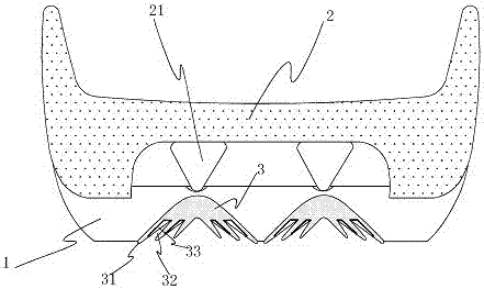
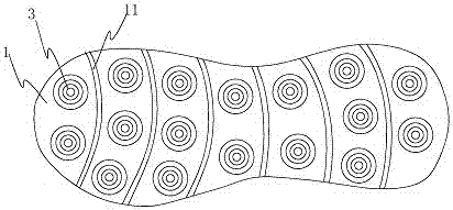
[0013] refer to Figure 1 to Figure 2 , Embodiment 1 of the present invention discloses that a non-slip shoe sole includes a large bottom 1 and a midsole 2 arranged on the large bottom. A plurality of conical protrusions 21 are provided, and the pointed ends of the conical protrusions 21 face the outsole 1; positioning grooves are provided on the upper surface of the outsole 1 corresponding to the positions of the conical protrusions hole, the pointed end of the conical protrusion 21 is placed in the positioning slot; the lower surface of the outsole 1 is provided with a conical slot at a position corresponding to the positioning slot, and The pointed end of the slot faces the positioning slot, and the conical anti-slip part 3 adapted to it is arranged in the conical slot, and the height of the conical anti-slip part 3 is greater than that of the conical slot The height of the conical anti-slip piece 3 is formed by stacking a plurality of conical anti-slip pieces 31 successiv...


PUM


Abstract

The invention relates to a shoe sole and particularly provides a skid-poof shoe sole which is excellent in skid-proof performance. The skid-proof shoe sole comprises an outsole and an insole, a containing groove is formed in the insole, a plurality of conical protrusions are arranged in the containing groove, and the sharp tip ends of the conical protrusions face the outsole; positioning groove holes are formed in the positions, corresponding to the conical protrusions, on the upper surface of the outsole, and the sharp tip ends of the conical protrusions are arranged in the positioning groove holes; conical groove holes are formed in the positions, corresponding to the positioning groove holes, on the lower surface of the outsole, the sharp tip ends of the conical groove holes face the positioning groove holes, and conical skid-proof pieces are arranged in the conical groove holes; each conical skid-proof piece is formed in the mode that a plurality of conical skid-proof plates are stacked and embedded, wherein the conical skid-proof plates share one sharp tip end, an extending gap is formed between the conical side walls of every two adjacent conical skid-proof plates, the heights of the conical skid-proof plates are gradually decreased from outside to inside in sequence, a storing groove is formed in the conical side wall of each conical skid-proof plate, and the storing groove of the next conical skid-proof plate can store the conical side wall of the previous conical skid-proof plate.

Description

technical field [0001] The invention relates to a shoe sole, in particular to a non-slip shoe sole. Background technique [0002] Nowadays, when people buy shoes, they no longer only consider the aesthetics of the shoes, but also consider the safety of the shoes, especially the anti-skid performance. When there is a liquid medium such as water on the ground, a liquid medium film is usually formed between the sole and the ground. This liquid medium film reduces the friction between the sole and the ground. It can be said that the friction is almost zero. At this time, It is easy for people to slip and fall and cause accidents, especially for the elderly and children, and the safety hazard is great. Especially in rainy days, ice and snow days, the ground is extremely wet and slippery, and the safety hazard is great. Therefore, in order to solve the aforementioned problems, the existing The technology sets raised structures on the soles, and gaps will be formed between the rai...

Claims


Application Information

Patent Timeline
Patent Type & Authority Applications(China)
IPC IPC(8): A43B13/22A43B13/26
CPCA43B13/22A43B13/26
Inventor 徐宏声
Owner 晋江巨人商贸有限公司
Why Eureka
Try Eureka