
Deburring device special for cabinet handle

A technology for deburring and handles, which is applied in the direction of grinding drive devices, grinding/polishing safety devices, and machine tools suitable for grinding workpiece edges, etc. It can solve the problems of low deburring efficiency, easy scratches on the surface, and affecting the appearance problems, to achieve the effect of convenient operation, good stability and high efficiency

Pending Publication Date: 2017-12-15
毛啸宇
View PDF8 Cites 4 Cited by
  • Summary
  • Abstract
  • Description
  • Claims
  • Application Information

AI Technical Summary

Problems solved by technology

[0003] In order to solve the problem of low deburring efficiency of cabinet handles in the prior art and easy scratches on the surface that affect the appearance, the present invention provides a special deburring device for cabinet handles, which can quickly remove the burrs of cabinet handles and has high deburring efficiency , will not cause scratches on cabinet handles

Method used


Image

  • Deburring device special for cabinet handle
  • Deburring device special for cabinet handle
  • Deburring device special for cabinet handle

Examples


Embodiment Construction

[0022] The present invention will be further described below in conjunction with the drawings and specific embodiments:

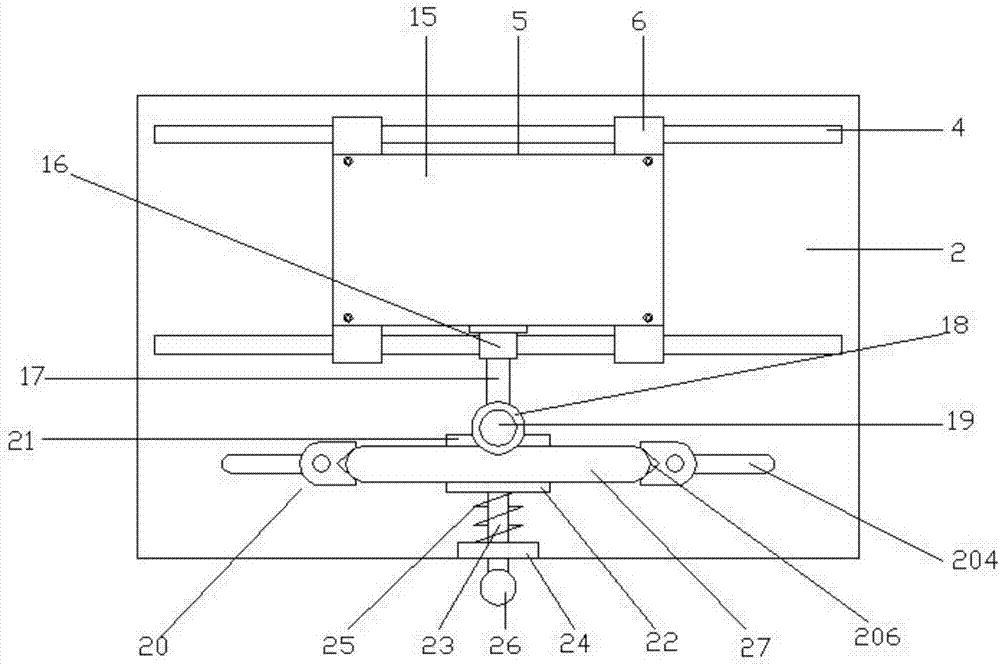
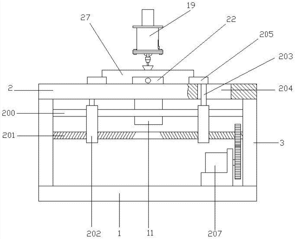
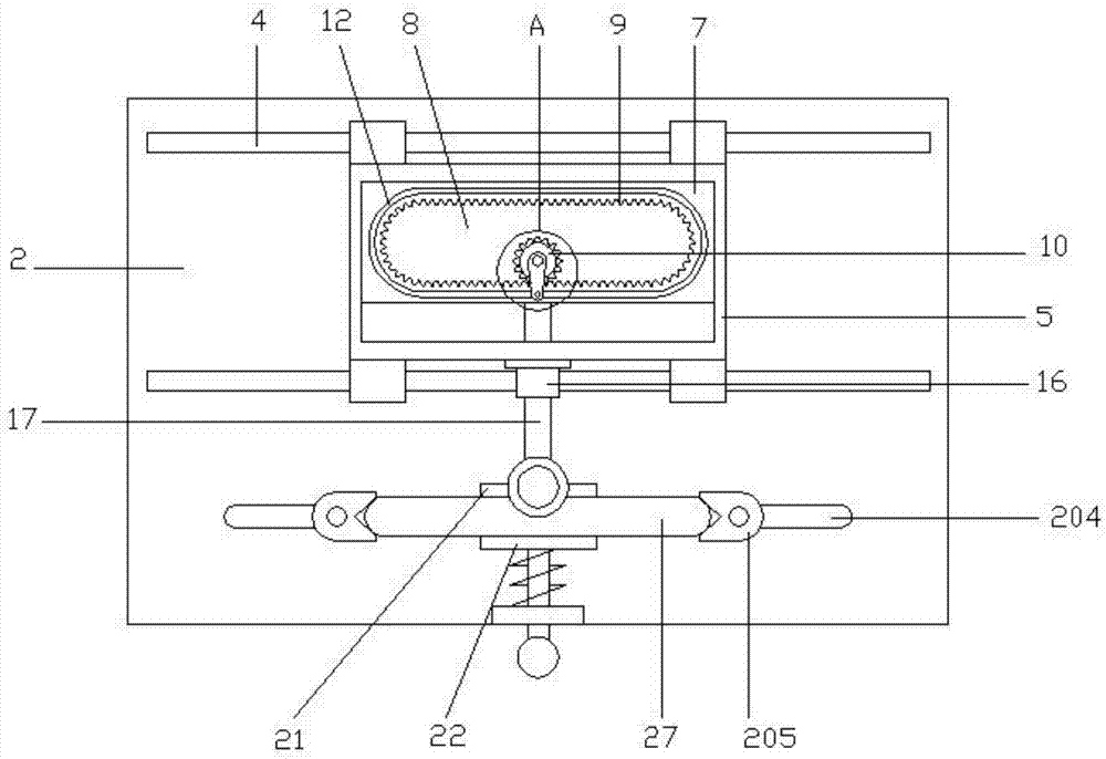
[0023] Such as figure 1 , figure 2 with image 3 The illustrated deburring device for cabinet handles includes a base 1 and a base plate 2. Both ends of the base are provided with support plates 3, the base plate is connected to the upper end of the support plate, and two parallel slide rails are provided on the top surface of the base plate. 4. There is a rectangular frame 5 between the two sliding rails. The side of the rectangular frame is slidably connected to the sliding rails through a slider 6. A sliding plate 7 is arranged in the rectangular frame, and the sliding direction of the sliding plate is perpendicular to the sliding direction of the rectangular frame; A waist-shaped hole 8 is provided. The inner wall of the waist-shaped hole is provided with a ring gear 9. The top surface of the base plate is provided with a gear 10 that extends into the wais...


PUM


Abstract

The invention relates to the technical field of machining and discloses a chamfering device special for a cabinet handle. The chamfering device comprises a base and a base plate, wherein two parallel sliding rails are arranged on the top surface of the base plate, a rectangular frame is arranged between the two sliding rails, the side face of the rectangular frame is in sliding connection with the sliding rails through a sliding block, and a sliding plate is arranged in the rectangular frame and is perpendicular to the rectangular frame in sliding direction. A kidney-shaped hole is formed in the sliding plate, the inner wall of the kidney-shaped hole is provided with a gear ring, a gear extending into the kidney-shaped hole and meshed with the gear ring is arranged on the top surface of the base plate, and a driving motor connected with the gear is arranged at the bottom of the base plate. A sliding sleeve is arranged on one side of the rectangular frame, a sliding rod is arranged in the sliding sleeve, the inner end of the sliding rod is fixedly connected with the side face of the sliding plate, the outer end of the sliding rod extends to form a connecting ring, an electric grinding mechanism is arranged on the upper side face of the connecting ring, and a handle positioning mechanism is also arranged on the base plate. The chamfering device has the advantages of being convenient to operate and good in stability and making the cabinet handle deburring efficiency high.

Description

Technical field [0001] The invention relates to the technical field of mechanical processing, in particular to a special deburring device for cabinet handles. Background technique [0002] A cabinet is a cabinet or box for storing kitchenware in the kitchen. The cabinet usually includes a cabinet body and a cabinet door. In order to facilitate the opening and closing of the cabinet door, a handle is usually set on the cabinet door. The handle is usually called a handle, such as figure 1 As shown in the figure, the handle on the cabinet door is made of aluminum alloy, and the whole is a cuboid structure, and its two end faces are curved surfaces, which is simple, generous and easy to manufacture. After this kind of handle is made by mechanical processing, there will be burrs at the edges, and the burrs will cut hands. Therefore, it is necessary to remove the burrs on the edges of the cabinet handle. However, there is currently no deburring equipment specifically for this kind of ha...

Claims


Application Information

Patent Timeline
Patent Type & Authority Applications(China)
IPC IPC(8): B24B9/04B24B41/06B24B47/20B24B41/02B24B55/00
CPCB24B9/04B24B41/02B24B41/06B24B47/20B24B55/00
Inventor 不公告发明人
Owner 毛啸宇
Learn More