A hanger for automatic hook removal

A technology for removing hooks and slings, which is applied in the field of automatic hook-removing slings, which can solve problems such as low work efficiency, tilting of the guide column box, complicated operation, etc., and achieve the effects of ensuring hoisting operations, preventing bolt displacement, and ensuring balance

Active Publication Date: 2019-12-06
NINGBO RUYI JOINT CO LTD
View PDF9 Cites 0 Cited by
  • Summary
  • Abstract
  • Description
  • Claims
  • Application Information

AI Technical Summary

Problems solved by technology

Lifting in this way requires manual loading and unloading of the hook every time, the operation is complicated, the work efficiency is low, and slipping between the lifting hole and the hook is easy to occur, which has potential safety hazards. There will be uneven force at the four corners, and the guide post box will tilt

Method used


Image

  • A hanger for automatic hook removal
  • A hanger for automatic hook removal
  • A hanger for automatic hook removal

Examples


Embodiment 1

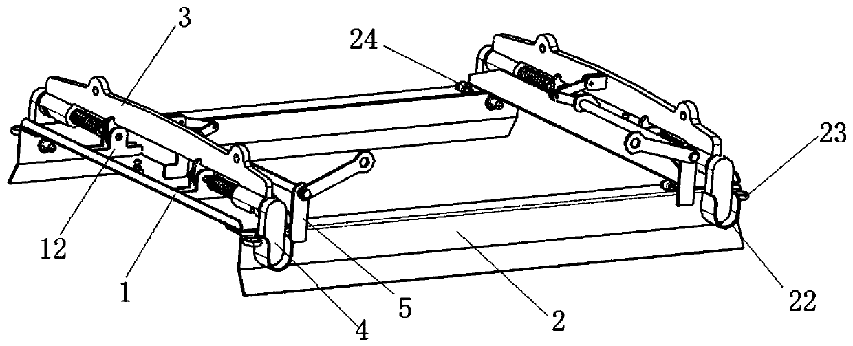
[0030] to combine figure 1 Shown, a kind of automatic dehook hanger, comprises frame and two hook devices that are installed on the frame, described frame is installed on the box that needs hoisting during hoisting, and frame wall and box wall are bonded, and described hook device and The box forms a fixed connection.

[0031] The two sets of opposite sides of the frame are respectively a first pair of sides 1 and a second pair of sides 2 , and the two hook devices are installed on the first pair of sides 1 respectively. The hook device includes a baffle 3 and two bolts 4 installed at both ends of the baffle 3 . The baffle 3 is connected to the first pair of sides 1 through a hinge 12, that is, the baffle 3 can rotate relative to the frame. When the baffle plate 3 rotates, it can drive the latch 4 to move back and forth, so as to complete the connection / disconnection operation of the spreader and the box.

[0032] When using the present invention to hoist the box body, the ...

Embodiment 2

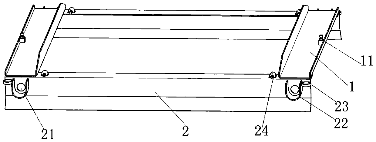
[0034] to combine figure 2 As shown, this implementation is based on the above-mentioned embodiments, the second opposite side 2 of the frame has a side wall bent downward, and the two ends of the side wall are provided with bolt holes 21 . The size of the frame is determined according to the size of the box that needs to be hoisted. When the sling is connected to the box, the side walls of the second opposite sides 2 are attached to the surface of the box, and the bolt hole 21 corresponds to the position of the lifting hole on the box.

[0035] The bottom of the side wall is bent outwards, and this bent structure can play a guiding role to facilitate the installation of the spreader frame on the box. Both ends of the second pair of sides 2 are equipped with rollers 24 to facilitate the movement of the frame on the box to determine the installation position. The frame structure can ensure the balance during the hoisting process of the box body, and it is not easy to tilt, el...

Embodiment 3

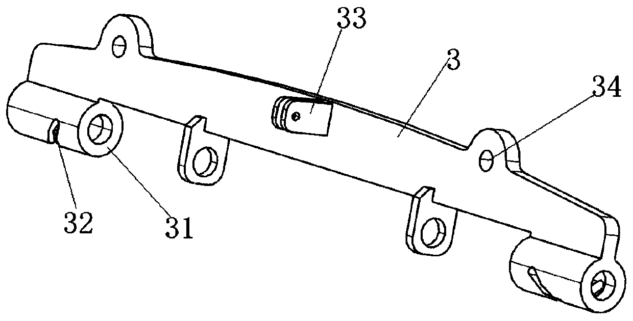
[0039] to combine image 3 As shown, this implementation is based on the above-mentioned embodiments, the two ends of the baffle plate 3 are provided with guide sleeves 31 , and the guide sleeves 31 are provided with spiral grooves 32 . A connecting seat 33 is provided in the middle of the baffle plate 3 . Two symmetrical hoisting holes 34 are provided on the baffle, and the hoisting holes 34 are used to connect the hooks of lifting tools. When hoisting, the baffle 3 will rotate upwards under force.

[0040] to combine Figure 4 As shown, the latch member 4 includes a guide post 41, a latch 42 and a pin seat 43, and the pin seat 43 connects the guide post 41 and the latch 42 from top to bottom, and the pin seat 43, the guide post 41 and the latch 42 will be Synchronized movement. Each pin seat 43 is all installed in the corresponding U-shaped guard plate 22, and each latch 42 has a corresponding latch hole 21, and the hook device realizes the loading and unloading operation...


PUM


Abstract

The invention discloses an automatic hook picking and hanging lifting appliance which comprises a frame and two hook devices. The two sets of opposite edges of the frame are first opposite edges and second opposite edges, two hook devices are installed on the first opposite edges, each hook device comprises a baffle and bolt pieces installed at the two ends of the baffle, the baffles are connected with the first opposite edges through hinges, and the baffles can drive the bolt pieces to move front and back during rotation. When the automatic hook picking and hanging lifting appliance is used for lifting boxes, the whole frame is installed at the tops of the boxes, a hoisting machine is connected with the baffles of the lifting appliance, the baffles are stressed to rotate during lifting, bolts are inserted into lifting holes of the boxes, automatic connection of the lifting appliance and the boxes can be achieved, and the lifting operation convenience and rapidness are greatly improved.

Description

technical field [0001] The invention relates to the field of hoisting equipment, in particular to an automatic hook removal sling. Background technique [0002] In the prior art, lifting holes are provided at the four corners of the box for the box that needs to be hoisted. The hoisting tool used for hoisting is a hook type sling, and the four hooks of the sling are respectively inserted into the four hanging holes of the box to form a lifting hole. connected, and then hoisted by a hoist. Lifting in this way requires manual loading and unloading of the hook every time, the operation is complicated, the work efficiency is low, and slipping between the lifting hole and the hook is easy to occur, which has potential safety hazards. There will be uneven force at the four corners, and the guide post box will tilt. [0003] In view of the above-mentioned defects, the inventor of the present invention has finally obtained a kind of automatic hook removal sling of the present inve...

Claims


Application Information

Patent Timeline
Patent Type & Authority Patents(China)
IPC IPC(8): B66C1/22B66C1/66
CPCB66C1/223B66C1/663
Inventor 张根社穆希辉杜峰坡赵子涵姜志保赵晓东
Owner NINGBO RUYI JOINT CO LTD
Why Eureka
Try Eureka