Electric hoist lifting hook device

An electric hoist and hook technology, which is applied in the field of hook application, can solve the problems of no protection measures for wire ropes, high quality requirements for fixing bolts, and large wear of wire ropes, so as to increase the load-bearing capacity and durability of use, and prevent goods from falling , the effect of improving the service life

Inactive Publication Date: 2017-12-15
池州市知识产权服务中心有限公司
0 Cites 3 Cited by

AI-Extracted Technical Summary

Problems solved by technology

[0002] With the rapid development of my country's industry, hoisting machinery has also been widely used. As the most common electric hoist hook device spreader in hoisting machinery, the hook plays a very important role in hoisting machinery. It is suspended on the steel wire rope with the help of pulley blocks and other ...

Method used

In one embodiment, for the above-mentioned bearing pendulum 31, a movable baffle 38 is movably connected on the bearing pendulum 31, and a fixed baffle 38 is provided between the movable baffle 38 and the suspension hook 6. spring clip 39 . The movable baffle described in the fixed column is effective, so that the goods will not fall off during use, increasing safety.
In summary, by means of the above-mentioned technical scheme of the present invention, when in use, the chain 3 enters from the chain outlet 22 described at one end, and comes out from the chain outlet 22 described at the other end, and the software at the bottom The bottom pad 16 is connected to the fixing column 35, the tooth block 14 engages the teeth 18, and the chain 3 is not easy to fall off through the meshing operation of the fixing column 35 and the teeth, which increases the safety of the present invention. The steel wire rope 20 is arranged in the steel wire protective sleeve 19, slides through the gears, and does not directly slide through the steel wire rope 20, so that the wear degree of the steel wire is effectively reduced, and the combination of multiple steel wire ropes 20 increases the cost. The load-bearing and durability of the invention, when the anti-blocking roller 23 is added, the resistance when the chain 3 slides is effectively reduced, so that the chain 3 slides more effortlessly, and the top of the hook 6 is provided with the The sliding ball 34 can use the hook 6 in different directions, making it more convenient to use, and the overweight alarm device 4 is provided on the universal bearing 5, which can effectively control the weight of the hoisted goods, and place the overweight Potential safety hazards are caused. Adding the movable baffle plate 38 on the hook can effectively prevent the goods from falling due to shaking during use. The present invention reduces the friction on the wire rope by setting the gear rotation, and at the same time, adding a protective cover greatly It reduces the loss of the wire rope, and at the same time strengthens...

Abstract

The invention discloses an electric hoist hook device, which comprises a shell, a multi-layer gear, a chain, an overweight alarm device, a universal bearing, a hook and a hexagonal bolt, and the shell includes a first shell and a second shell , the first housing and the second housing are provided with a number of hexagonal screw holes, the hexagonal bolts connect the first housing and the second housing through the hexagonal screw holes, so The cavity formed by the first casing and the second casing is divided into cavity one and cavity two. Beneficial effects: the invention reduces the friction on the steel wire rope by setting the gear to rotate, and at the same time, adding a protective cover greatly reduces the loss of the steel wire rope, and at the same time strengthens the weighing weight of the chain through multiple steel wire ropes, so that the steel wire rope in use can disperse the weight, effectively The burden of a single wire rope is reduced, and the service life is greatly improved, and the hook can be rotated universally, which makes it more convenient to use, and a baffle is added to prevent the goods from falling, which increases safety.

Application Domain

Winding mechanismsLoad-engaging elements

Technology Topic

EngineeringWire rope +4

Image

  • Electric hoist lifting hook device
  • Electric hoist lifting hook device
  • Electric hoist lifting hook device

Examples

  • Experimental program(1)

Example Embodiment

[0026] The technical solutions in the embodiments of the present invention will be clearly and completely described below in conjunction with the accompanying drawings in the embodiments of the present invention. Obviously, the described embodiments are only a part of the embodiments of the present invention, rather than all the embodiments. Based on the embodiments of the present invention, all other embodiments obtained by a person of ordinary skill in the art fall within the protection scope of the present invention.
[0027] According to an embodiment of the present invention, an electric hoist hook device is provided.
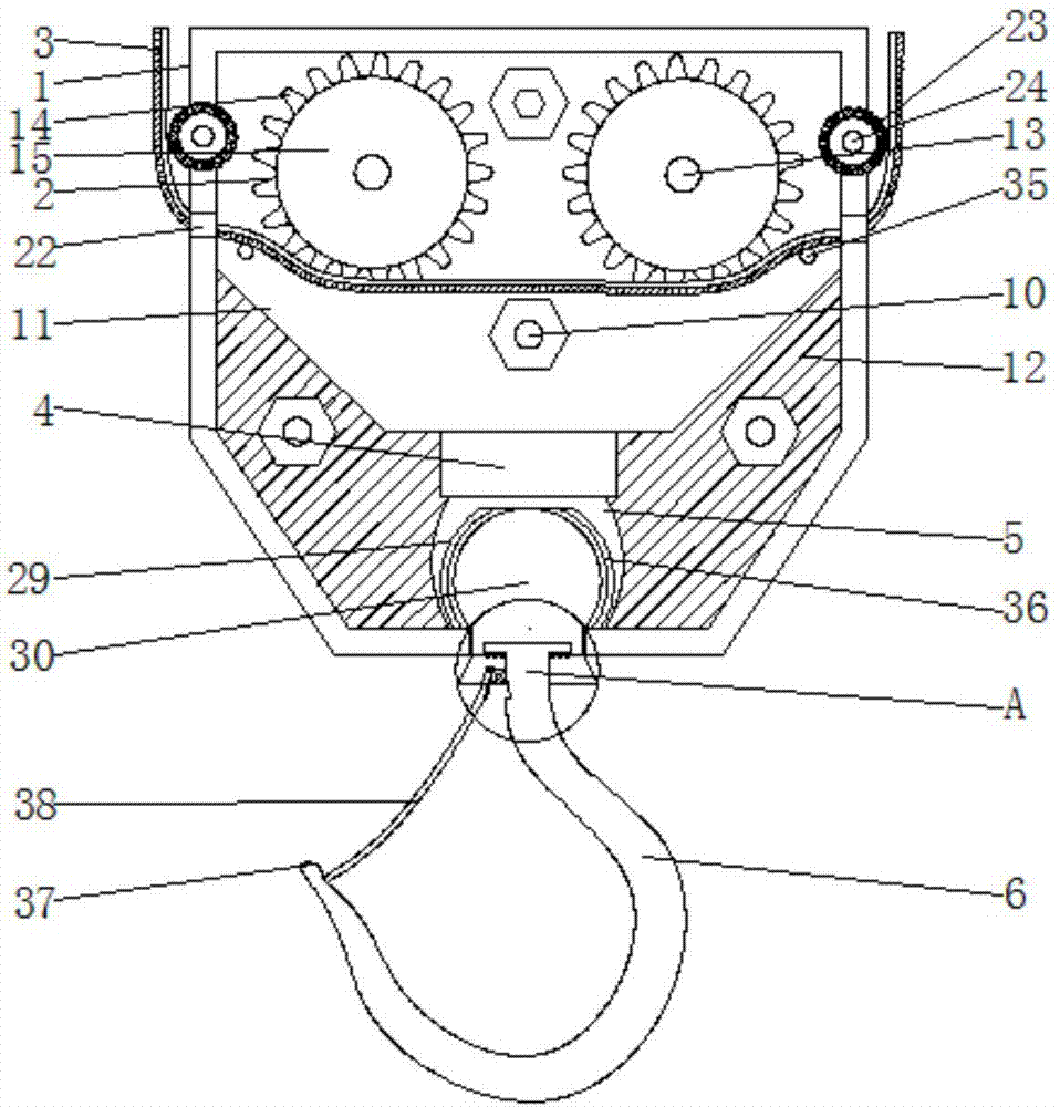
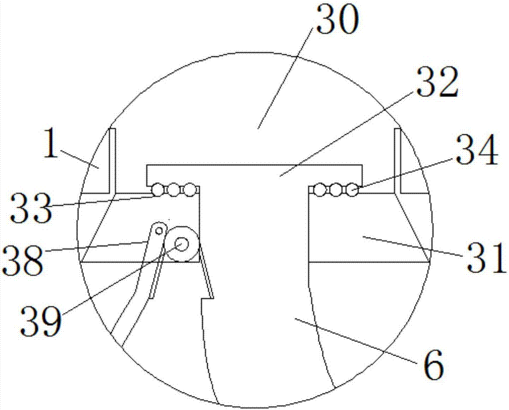
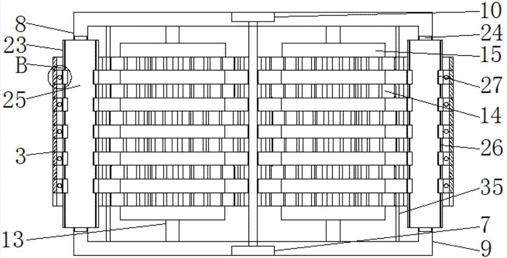
[0028] Such as Figure 1-5 As shown, the electric hoist hook device according to the embodiment of the present invention includes a housing 1, a multi-layer gear 2, a chain 3, an overweight alarm device 4, a universal bearing 5, a hook 6 and a hexagonal bolt 7. The housing 1 Contains a first housing 8 and a second housing 9. A number of hexagonal screw holes 10 are provided on both the first housing 8 and the second housing 9, and the hexagonal bolts 7 pass through the hexagonal screw holes. 10 Connect the first housing 8 and the second housing 9, and the cavity formed by the first housing 8 and the second housing 9 is divided into cavity one 11 and cavity two 12 .
[0029] The multi-layer gear 2 is movably connected to the inner wall of the cavity 11 through a fixing bolt 13 provided thereon. The multi-layer gear 2 is divided into a tooth block 14 and a smooth block 15, and the chain 3 includes The soft bottom pad 16, the tooth connecting seat 17, the tooth 18, the steel wire protective sleeve 19 and the steel wire 20, the tooth 18 is fixedly connected to the upper surface of the tooth connecting seat 17, and the adjacent teeth are connected Thread openings 21 are opened between the seats 17, the steel wire rope 20 is inserted into the steel wire protective sleeve 19, and the steel wire protective sleeve 19 and the tooth connecting seat 17 are evenly staggered and connected to the soft bottom pad 16 The upper surface of the tooth block 14 and the tooth tooth 18 and the steel wire protection sleeve 19 and the smooth block 15 respectively engage correspondingly, and the two ends of the chain 3 are respectively arranged in the housing 1 The upper chain outlet 22 extends out of the housing 1. Both sides of the housing 1 are located above the chain outlet 22 and are provided with anti-block rollers 23. The anti-block rollers 23 include connecting posts 24, The roller 25, the string rod 26 and the movable wheel 27, the connecting column 24 is fixedly inserted on the housing 1, the roller 25 is sleeved on the connecting column 24, and the roller 25 is fixedly connected to a number of The string rod 26 is movably connected to the movable wheel 27 on the string rod 26, a number of balls 28 are clamped on the outer surface of the movable wheel 27, and the movable wheel 27 is slidingly connected to the smooth block 15 correspondingly.
[0030] The overweight alarm device 4 is arranged in the cavity two 12, and the bottom of the overweight alarm device 4 is connected to the universal bearing 5. The universal bearing 5 includes a bearing seat 29 and a shaft seat 30. The shaft seat 30 A bearing pendulum 31 is connected to the bottom, the hanging hook 6 is movably connected in the bearing pendulum 31, a turntable 32 is arranged on the top of the hanging hook 6, and the positions corresponding to the bearing pendulum 31 at the bottom of the turntable 32 are respectively provided A number of sliding grooves 33, and a number of sliding beads 34 are arranged in the sliding grooves 33.
[0031] In one embodiment, for the cavity 11 described above, a plurality of fixing posts 35 are fixedly connected to the inner wall of the cavity 11, and the chain 22 is arranged on it. It is ensured that the position of the chain 3 during sliding does not change, and the normal operation of the sliding work is ensured.
[0032] In one embodiment, for the above-mentioned steel wire protective sleeve 19, the steel wire protective sleeve 19 is a polymer rubber sleeve. The use of polymer rubber makes the steel wire protective sleeve 19 more durable and effectively protects the steel wire rope 20.
[0033] In one embodiment, for the tooth 18 and the tooth block 14, the surfaces of the tooth 18 and the tooth block 14 are coated with an anti-wear layer. Effectively reduce the damage to parts caused by friction and greatly increase the service life of parts.
[0034] In an embodiment, for the movable wheel 27 described above, a number of balls 28 are clamped on the outer surface. As a result, the resistance of the chain 3 in use is lower and the sliding movement is smoother.
[0035] In one embodiment, for the above-mentioned overweight alarm device 4, the overweight alarm device 4 uses a Hall element inside.
[0036] In one embodiment, for the bearing seat 29 and the shaft seat 30 described above, an anti-wear pad 36 is provided between the bearing seat 29 and the shaft seat 30. The use of the anti-wear pad 36 can effectively increase the service life of the universal bearing, and the universal bearing is more convenient in use.
[0037] In one embodiment, for the hook 6 described above, the hook head of the hook 6 is provided with a raised point 37.
[0038] In one embodiment, for the above-mentioned bearing pendulum 31, a movable baffle 38 is movably connected to the bearing pendulum 31, and a fixed spring clamp 39 is provided between the movable baffle 38 and the hook 6 . The movable baffle plate is effectively fixed, so that the goods will not fall off during use, which increases safety.
[0039] In an embodiment, for the movable baffle 38 described above, the end of the movable baffle 38 away from the bearing pendulum 31 is clamped on the raised point 37. The movable baffle can be effectively blocked, and the opening of the movable baffle can prevent the goods from being scattered and causing accidents.
[0040] In summary, with the above technical solution of the present invention, when in use, the chain 3 enters from the chain outlet 22 at one end and exits from the chain outlet 22 at the other end. The soft bottom pad 16 Connected to the fixed post 35, the tooth block 14 engages the tooth 18, and the engagement of the fixed post 35 and the tooth makes the chain 3 difficult to fall off, which increases the safety of the present invention. The steel wire rope 20 Set in the steel wire protective sleeve 19, sliding through the gears, not directly sliding through the steel wire rope 20, effectively reducing the wear of the steel wire, and the combination of a plurality of the steel wire ropes 20 increases the bearing capacity of the present invention. For weight and durability, the anti-block roller 23 is added to effectively reduce the resistance of the chain 3 when sliding, making the chain 3 slide more labor-saving, and the sliding bead 34 is arranged on the top of the hook 6 , The hook 6 can be used in different directions, making it more convenient to use, and the overweight alarm device 4 is provided on the universal bearing 5 to effectively control the weight of the lifted goods, and placing overweight causes safety hazards The addition of the movable baffle 38 on the hook can effectively prevent the goods from falling due to shaking during activation. The present invention reduces the friction on the wire rope by setting the gear rotation, and at the same time, the addition of a protective cover greatly reduces the wire rope At the same time, the weight of the chain is strengthened by multiple steel wire ropes, so that the steel wire rope in use can distribute the weight, effectively reducing the burden of a single wire rope, greatly improving the service life, and the hook can rotate in universal directions, making the The middle is more convenient, and the baffle is added to prevent the goods from falling, which increases the safety.
[0041] The above descriptions are only preferred embodiments of the present invention and are not intended to limit the present invention. Any modification, equivalent replacement, improvement, etc. made within the spirit and principle of the present invention shall be included in the present invention. Within the scope of protection.

PUM

no PUM

Description & Claims & Application Information

We can also present the details of the Description, Claims and Application information to help users get a comprehensive understanding of the technical details of the patent, such as background art, summary of invention, brief description of drawings, description of embodiments, and other original content. On the other hand, users can also determine the specific scope of protection of the technology through the list of claims; as well as understand the changes in the life cycle of the technology with the presentation of the patent timeline. Login to view more.

Similar technology patents

Trusted computing platform chip applicable to mobile communication equipment and authentication method thereof

InactiveCN101986641Aimprove securityachieve security
Owner:HANGZHOU SYNOCHIP DATA SECURITY TECH CO LTD

Hidden frame glass curtain wall structure and method for mounting same

InactiveCN107829513AImprove decorationimprove security
Owner:XINCHANG SICHUANG DESIGN CONSULTING CO LTD

Nano metal silver antibiotic paint and its preparing method

InactiveCN1616559Aimprove security
Owner:RESEARCH INSTITUTE OF TSINGHUA UNIVERSITY IN SHENZHEN

Classification and recommendation of technical efficacy words

  • reduce wear
  • improve security

Pesticide micro-capsule granules and preparation method thereof

InactiveCN102100229Alow toxicityimprove security
Owner:联合国南通农药剂型开发中心 +1

Method for achieving user authentication by utilizing camera

InactiveCN103678984Aimprove securityGuaranteed picture quality
Owner:湖北微模式科技发展有限公司
Why Eureka
Try Eureka