Eureka AIR delivers breakthrough ideas for toughest innovation challenges, trusted by R&D personnel around the world.

Integrated electric air compressor and fuel battery air inlet system with compressor

An air compressor and compressor technology, applied in fuel cells, electric components, electrical components, etc., can solve the problems of difficult layout of external cables and pipelines, low integration, electromagnetic interference, etc., to reduce electromagnetic interference and reduce assembly Complexity, effect of reducing impact

Active Publication Date: 2017-12-15
ZHONGSHAN BROAD OCEAN +1
View PDF8 Cites 2 Cited by
  • Summary
  • Abstract
  • Description
  • Claims
  • Application Information

AI Technical Summary

Problems solved by technology

[0006] An object of the present invention is to provide an integrated electric air compressor and a fuel cell air intake system using it, so as to solve the problems in the prior art that the components of the air compressor are separated and i

Method used


Image

  • Integrated electric air compressor and fuel battery air inlet system with compressor
  • Integrated electric air compressor and fuel battery air inlet system with compressor
  • Integrated electric air compressor and fuel battery air inlet system with compressor

Examples


Embodiment 1

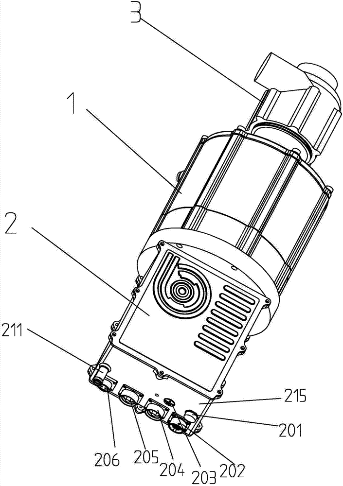
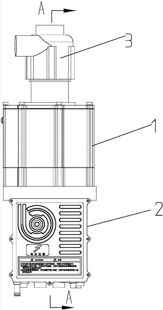
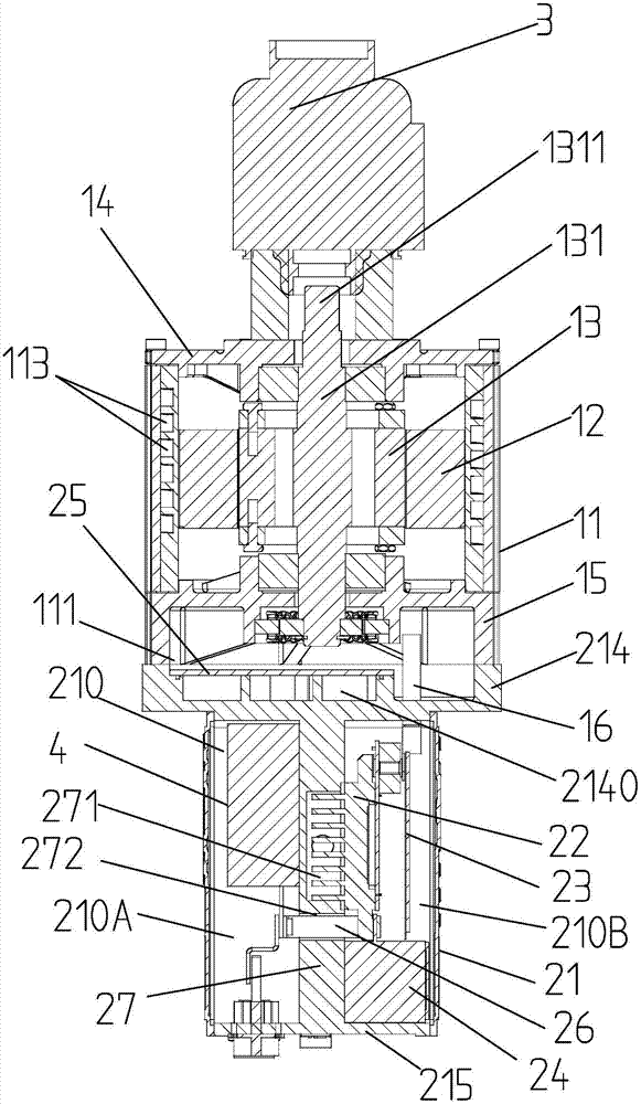
[0057] Such as Figure 1 to Figure 14 As shown, this embodiment provides an integrated electric air compressor, including a motor 1, a motor controller 2, and a compressor assembly 3. The motor 1 and the motor controller 2 form a motor drive system, and the motor 1 is a compressor The assembly 3 provides power. The motor 1 includes a housing 11 with a first liquid cooling channel 113 with a first liquid inlet 111 and a first liquid outlet 112, a stator assembly 12, a rotor assembly 13, a front end cover 14 and a rear end cover 15. The stator assembly 12 and the rotor assembly 13 are installed in the casing 11. The rotor assembly 13 includes a rotating shaft 131, and the end of the rotating shaft 131 extends from the front end cover to form a shaft extension end 1311;

[0058] The motor controller 2 is used to control the operation of the motor, and includes a drive module 22, a control circuit board 23, a capacitor module 24, a box with a second liquid cooling channel 213 with a ...

Embodiment 2

[0076] Such as Figure 15 As shown, a fuel cell air intake system of the present invention includes an air filter, a muffler, an integrated electric air compressor, an air cooler, and a humidifier. The external cold air passes through the filter, muffler, and integrated electric air The compressor, air cooler and humidifier provide compressed air to the fuel cell stack. Such as Figure 16 As shown, the self-starting integrated air compressor adopts the integrated electric air compressor described in the first embodiment, and it also includes a low-voltage power supply, which passes through a DC-DC converter 4 installed in the box. The conversion into high voltage provides the working energy of the start-up phase to the motor drive system.

[0077] Such as Figure 17 As shown, the DC-DC converter is connected with a control switch 200. When the fuel cell system reaches the normal operating voltage, the DC-DC converter 4 is automatically disconnected by the control switch 200, and ...


PUM


Abstract

The invention discloses an integrated electric air compressor and a fuel battery air inlet system with the compressor. According to the integrated electric air compressor, a compressor assembly, a motor and a motor controller are integrated with a DC-DC converter into a whole, the DC-DC converter is arranged in a box body of the motor controller, the motor controller is connected to a rear end cover of the motor, the compressor assembly is mechanically connected with the motor, the air compressor has the self-starting function, the use number of inserting parts and pipelines can be reduced, the integration degree and the modularization degree are high, the size is compact, the mounting is facilitated, the complex degree and the manufacturing cost of the system are reduced, the part number is reduced, the influence of exposed pipelines on the system are reduced, the system assembly complexity is reduced, and electromagnetic interference is reduced.

Description

Technical field: [0001] The invention relates to an integrated electric air compressor, in particular to a fuel cell air intake system in an electric vehicle. Background technique: [0002] The fuel cell system uses the electrochemical reaction between the hydrogen stored in the gas cylinder and the oxygen from the air to generate electrical energy to provide a source of power for electrical equipment, generally including a fuel cell stack and a fuel cell air intake system. The fuel cell air intake system includes an air compressor, an air filter, a muffler, and a humidifier. The air compressor is used to compress air and provide compressed air to the battery stack; an air filter is used to purify the air and block the air The dust and other impurities enter the air intake system; the muffler eliminates the noise generated by the sharp air flow; and the humidifier uses the moisture generated in the battery stack to humidify the compressed air. [0003] The air compressor includes ...

Claims


Application Information

Patent Timeline
IPC IPC(8): F04B35/04H02K11/33H02K5/20H02K9/193H02J9/06H01M8/04089
CPCH01M8/04089H02J9/061H02K9/193H02K11/33F04B35/04H02K5/203Y02E60/50
Inventor 邓佳朱太荣韦冬冬赵勇富
Owner ZHONGSHAN BROAD OCEAN
Why Eureka
Eureka Blog
Learn More