Test device for determining life of steel wire under coupling effect of corrosion and fatigue, and method thereof

A corrosion fatigue and test device technology, which is applied in the direction of measuring device, testing material strength by applying repetitive force/pulsation force, testing wear resistance, etc., can solve problems such as multiple steel wire test, unsteel wire life test evaluation, etc.

Active Publication Date: 2017-12-15
SOUTHEAST UNIV
View PDF6 Cites 13 Cited by
  • Summary
  • Abstract
  • Description
  • Claims
  • Application Information

AI Technical Summary

Problems solved by technology

[0004] Purpose of the invention: the purpose of this invention is to provide a test device for measuring the life of a steel wire under the coupling effect of corrosion fatigue, to solve the problem that the existing fatigue test cannot simultaneously test multiple steel wires under the coupling effect of corrosion fatigue, another purpose of the present invention It provides a test method for measuring the life of steel wire under the coupling effect of corrosion fatigue, and solves the problem that the life test and evaluation of steel wire under different corrosion-fatigue conditions are not carried out in the prior art

Method used


Image

  • Test device for determining life of steel wire under coupling effect of corrosion and fatigue, and method thereof
  • Test device for determining life of steel wire under coupling effect of corrosion and fatigue, and method thereof
  • Test device for determining life of steel wire under coupling effect of corrosion and fatigue, and method thereof

Examples


Embodiment Construction

[0021] The present invention will be further described below in conjunction with accompanying drawing.

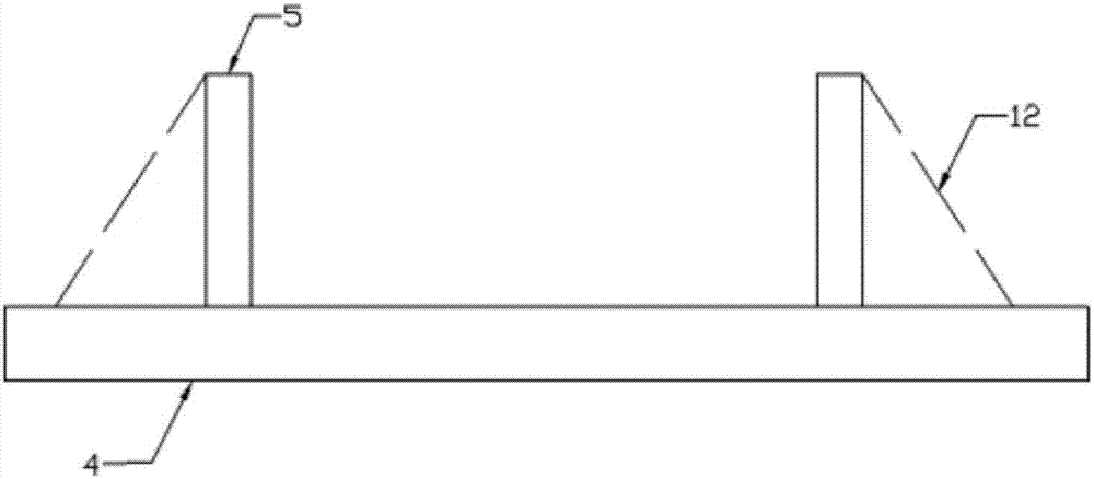
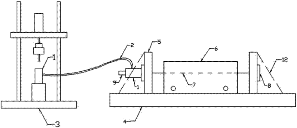
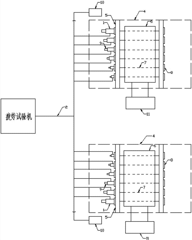
[0022] Such as figure 1 As shown, the reaction frame is designed according to the size and quantity of the steel wires. Its strength can meet the fatigue of multiple steel wires at the same time. It is welded by steel plates, including the column 5, the brace 12 and the support 4. The diagonal brace 12 is connected and fixed to the support 4, and the side of the column 5 is connected to the hydraulic jack 1, and the hydraulic jack 1 is connected to the oil circuit 2. The number of the columns 5 is two, and the two columns are vertically arranged on the support 4 at intervals. Above, the column 5 has a round hole to connect the anchor 8, the anchor 8 is used to fix the hydraulic jack 1 and the steel wire 7, and the hydraulic jack 1 is also provided with a sensor 9; image 3 As shown, the corrosion circulation container is made up of the corrosion container 6, the circulatio...


PUM


Abstract

The invention discloses a test device for determining the life of a steel wire under the coupling effect of corrosion and fatigue, and a method thereof. The device comprises reaction frames, a corrosive circulating container and a fatigue test machine, the reaction frames are respectively connected with the fatigue test machine through oil ways, every reaction frame comprises stand columns, inclined struts and a bearer, the stand columns are respectively connected and fixed to the bearer through the inclined struts, one side of every stand column is connected with a plurality of hydraulic jacks, and the hydraulic jacks are connected with the oil ways; and the corrosive circulating container is arranged between the stand columns of the reaction frame, the corrosive circulating container comprises a corrosive container, a circulating container and a pipeline for connecting the corrosive container with the circulating container, and the corrosive container is provided with a circular hole for a steel wire to be tested to traverse through. The device and the method are developed on the basis of traditional fatigue test and corrosion test, are used for exploring the damage mechanism of the steel wire under the coupling of the corrosion and the fatigue, and lay a foundation for the assessment of the life of practical bridge engineering.

Description

technical field [0001] The invention belongs to the field of corrosion and fatigue intersecting tests, in particular to a test device and method for measuring the service life of steel wires under the coupling action of corrosion fatigue. Background technique [0002] The cable-stayed cables of long-span cable-stayed bridges bear most of the constant and live loads of the bridge and transmit them to the tower columns. The life of the cables is basically equal to the life of the entire bridge. The main cable of the suspension bridge bears all the load of the bridge and cannot be replaced during the service period. The vertical pressure of the main cable is evenly transmitted from the main cable saddle to the cable tower, and its service life is basically the same as that of the bridge. The prestressed anchor cables or anchor rods of long-term bridge anchoring and support projects also directly bear the upper load and transmit it to the foundation, and their service life is al...

Claims


Application Information

Patent Timeline
Patent Type & Authority Applications(China)
IPC IPC(8): G01N3/36G01N3/56G01N17/00
CPCG01N3/36G01N3/567G01N17/002G01N17/006G01N2203/0073G01N2203/028G01N2203/0048G01N2203/0005
Inventor 王莹张文辉吴佰建
Owner SOUTHEAST UNIV
Why Eureka
Try Eureka