New energy vehicle device

A technology for new energy vehicles and charging piles, which is applied in the direction of coupling devices, parts of connection devices, and connection/disconnection of connection devices. It can solve problems such as difficult operation, power failure of new energy vehicles, and exposure of electric cavity Increase the safety of use and the effect of safe and stable power supply

Inactive Publication Date: 2017-12-15
宣城尤达美智能科技有限公司
View PDF8 Cites 1 Cited by
  • Summary
  • Abstract
  • Description
  • Claims
  • Application Information

AI Technical Summary

Problems solved by technology

[0002] The battery in the car needs to be charged before the new energy vehicle is used. Nowadays, the charging of the new energy vehicle is basically to insert the plug connected to it directly into the electric cavity of the charging pile body, and the charging pile body is connected to the mains. It will always be in the power-on state. Although this kind of cooperation is relatively simple and convenient to operate, the length of the wires between the plug-in body and the new energy vehicle is different. After the plug-in body is inserted into the lead cavity, there is no other locking device for the plug-in. When the wire is accidentally kicked and bumped, it will cause the plug-in body to be separated from the lead cavity, which will cause a sudden power failure of the new energy vehicle, and in serious cases will directly cause damage to the new energy vehicle. Therefore, the existing The matching method between the plug-in body and the lead-in cavity has unstable power supply connection. In addition, when the new energy vehicle is not in use, the plug-in body is often pulled out from the lead-in cavity, which will cause the lead-in cavity to be damaged. Exposed, there is a big safety hazard, and when the plug is pulled out from the lead cavity, a large force needs to be applied, which is not easy to operate

Method used


Image

  • New energy vehicle device
  • New energy vehicle device
  • New energy vehicle device

Examples


Embodiment Construction

[0020] The preferred embodiments of the present invention will be described in detail below in conjunction with the accompanying drawings, so that the advantages and features of the present invention can be more easily understood by those skilled in the art, and the protection scope of the present invention will be defined more clearly.

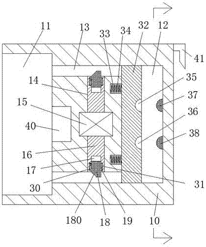
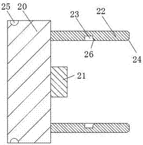
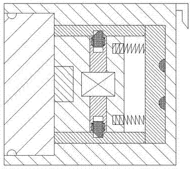
[0021] See Figure 1-5 The new energy vehicle device shown includes a charging pile body 10 and a charging gun 20 for mating connection with the charging pile body 10. An insertion body 21 is provided at the midpoint of the right end of the charging gun 20. On the right end surface of the gun 20, two coupling plates 22 are symmetrically provided on the front and rear sides of the insert body 21. The inner end surface of each of the two coupling plates 22 is provided with a locking groove 23, and the two A first inclined surface 26 is provided on the inner side of the right end of each of the locking grooves 23, and a second inclined surface 24 i...


PUM


Abstract

The invention discloses a new energy vehicle device, comprising a charging pile body and a charging gun used for cooperating and connecting with the charging pile body. Two connecting plates are mutually symmetrically arranged on the front and rear sides of the plug body, a locking groove is formed on the inner end surface of each of the two connecting plates, and the right end of each of the two locking grooves is A first inclined surface is arranged on the inner side of the two connecting plates, and a second inclined surface is arranged on the outer side of the right end surface of each of the two connecting plates. The present invention has simple structure, high power supply stability, and effectively reduces electric shock accidents in existing life. The occurrence of the charging gun ensures the safety of people's lives, and the unlocking of the charging gun is realized by motor control, which can simultaneously realize the unlocking of the charging gun and the cooperating connection between the plug-in body and the charging cavity, and the operation of power-on and power-off of the whole device is simple and convenient.

Description

Technical field [0001] The invention relates to the field of new energy vehicles, in particular to a new energy vehicle device. Background technique [0002] New energy vehicles need to charge the battery in the car before they are used. Nowadays, the charging of new energy vehicles basically involves directly inserting the plug connected to it into the charging cavity of the charging pile body, and the charging pile body is connected to the mains It will always be energized. Although this matching method is relatively simple and convenient to operate, the length of the wire between the plug body and the new energy vehicle is different, and there is no other locking device after the plug body is inserted into the electric cavity. When the wire is accidentally kicked and hit by accident, the plug body will be separated from the electric cavity, which will cause the sudden power failure of the new energy vehicle. In severe cases, it will directly cause the damage of the new energy ...

Claims


Application Information

Patent Timeline
Patent Type & Authority Applications(China)
IPC IPC(8): H01R13/629H01R13/639H01R13/642H01R43/26
CPCH01R13/629H01R13/639H01R13/642H01R43/26
Inventor 李维传
Owner 宣城尤达美智能科技有限公司
Why Eureka
Try Eureka